User Manual
> Product Information
Mechanical Structure#
Joint Diagram#
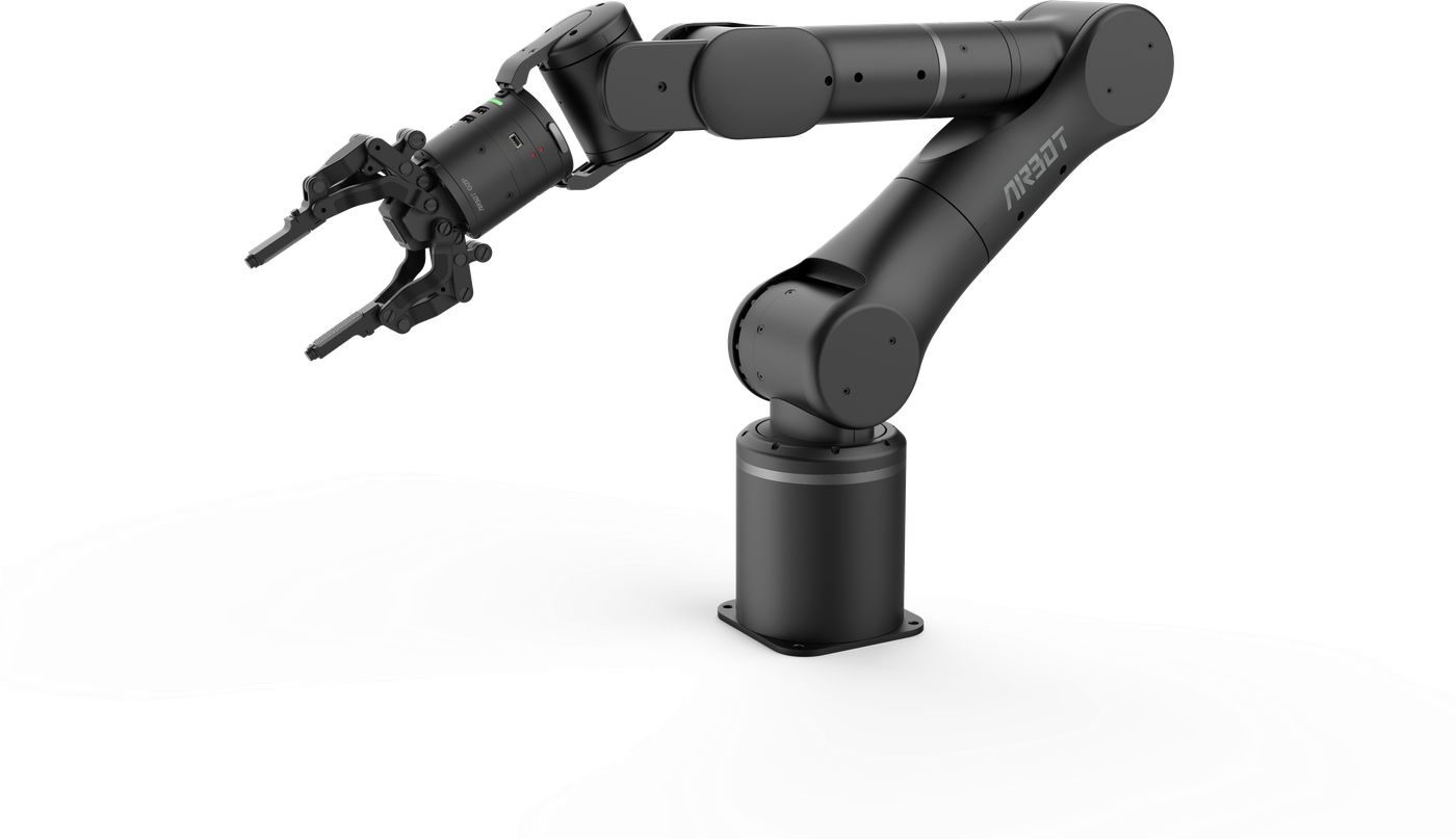
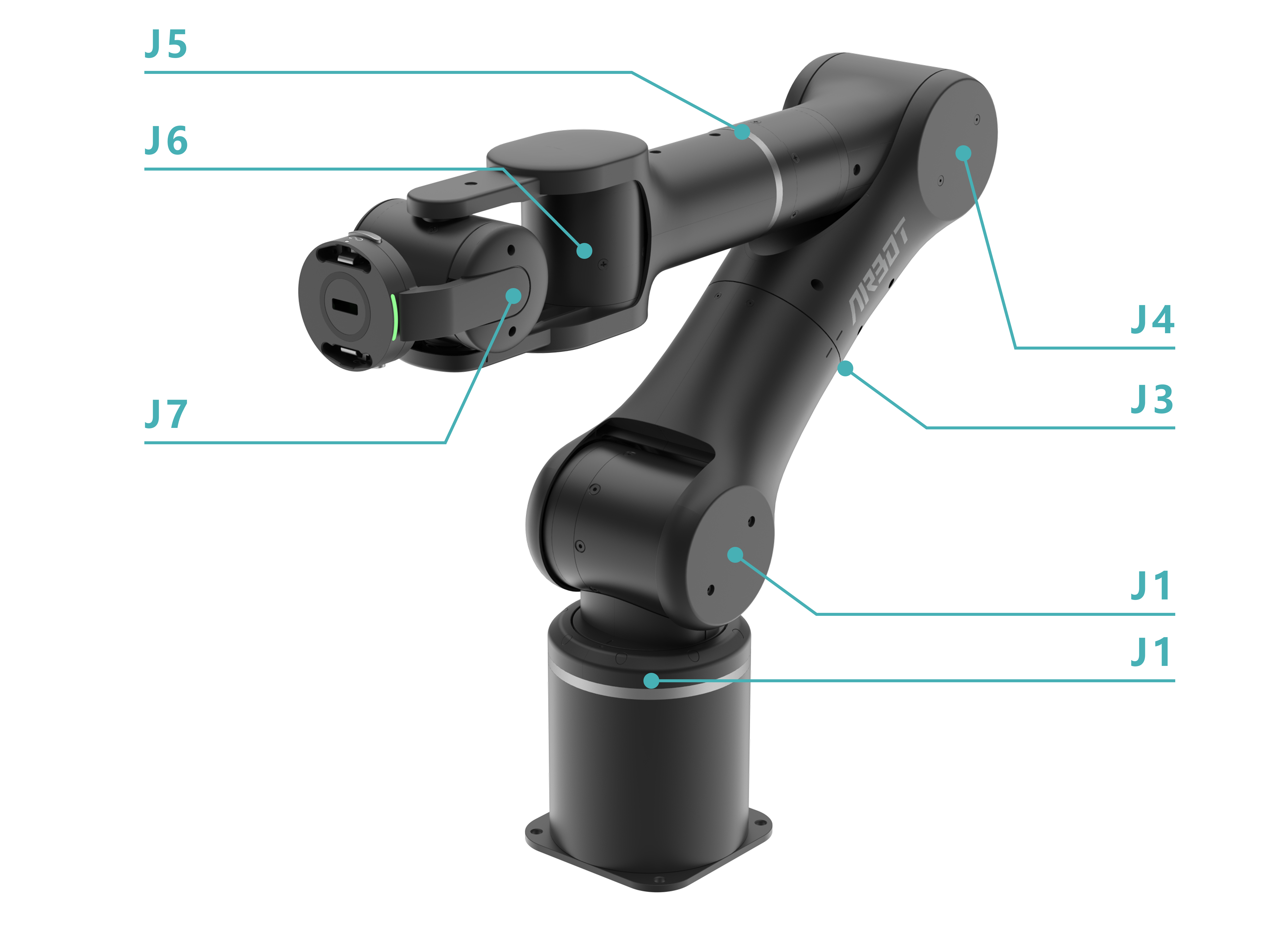
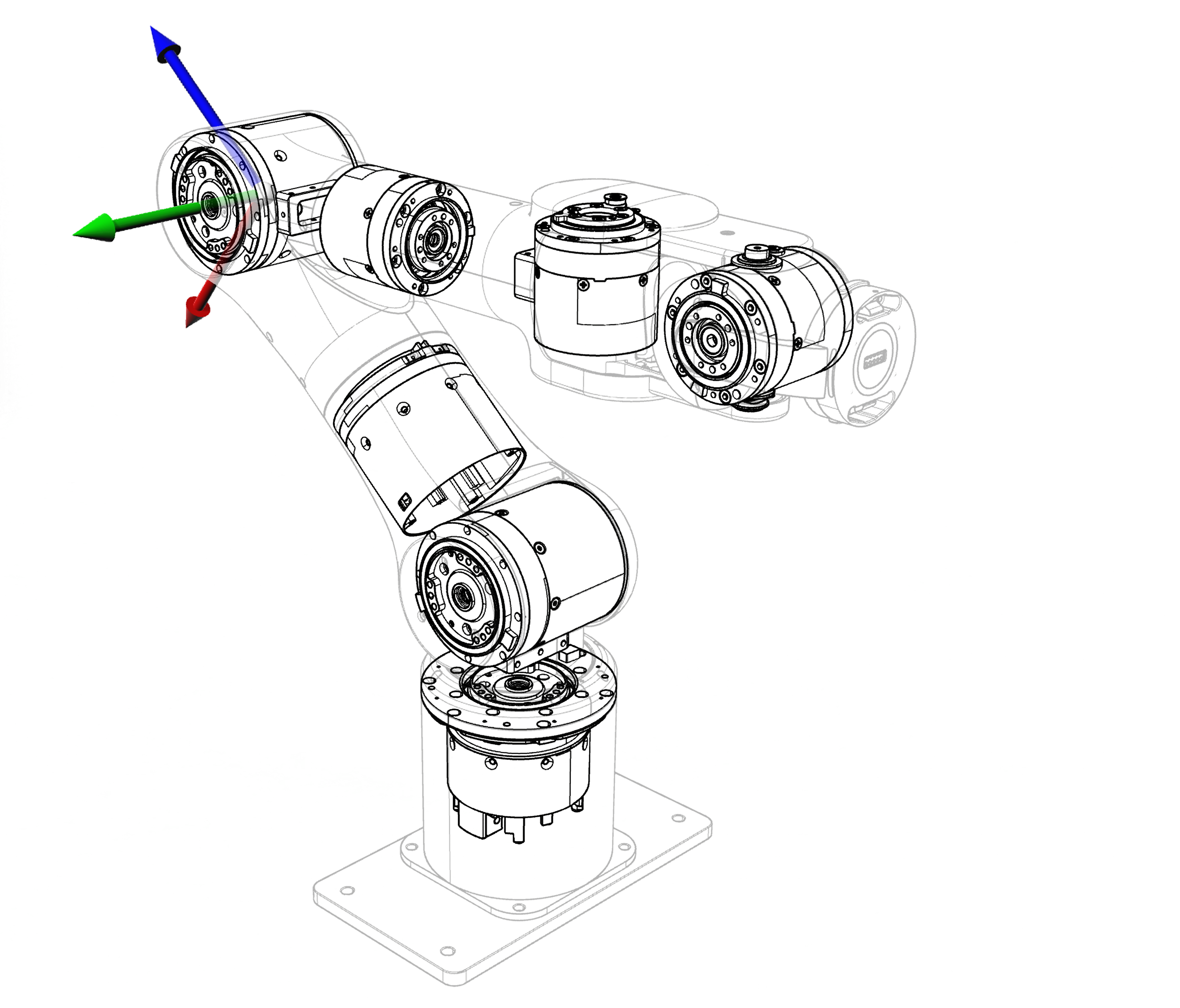
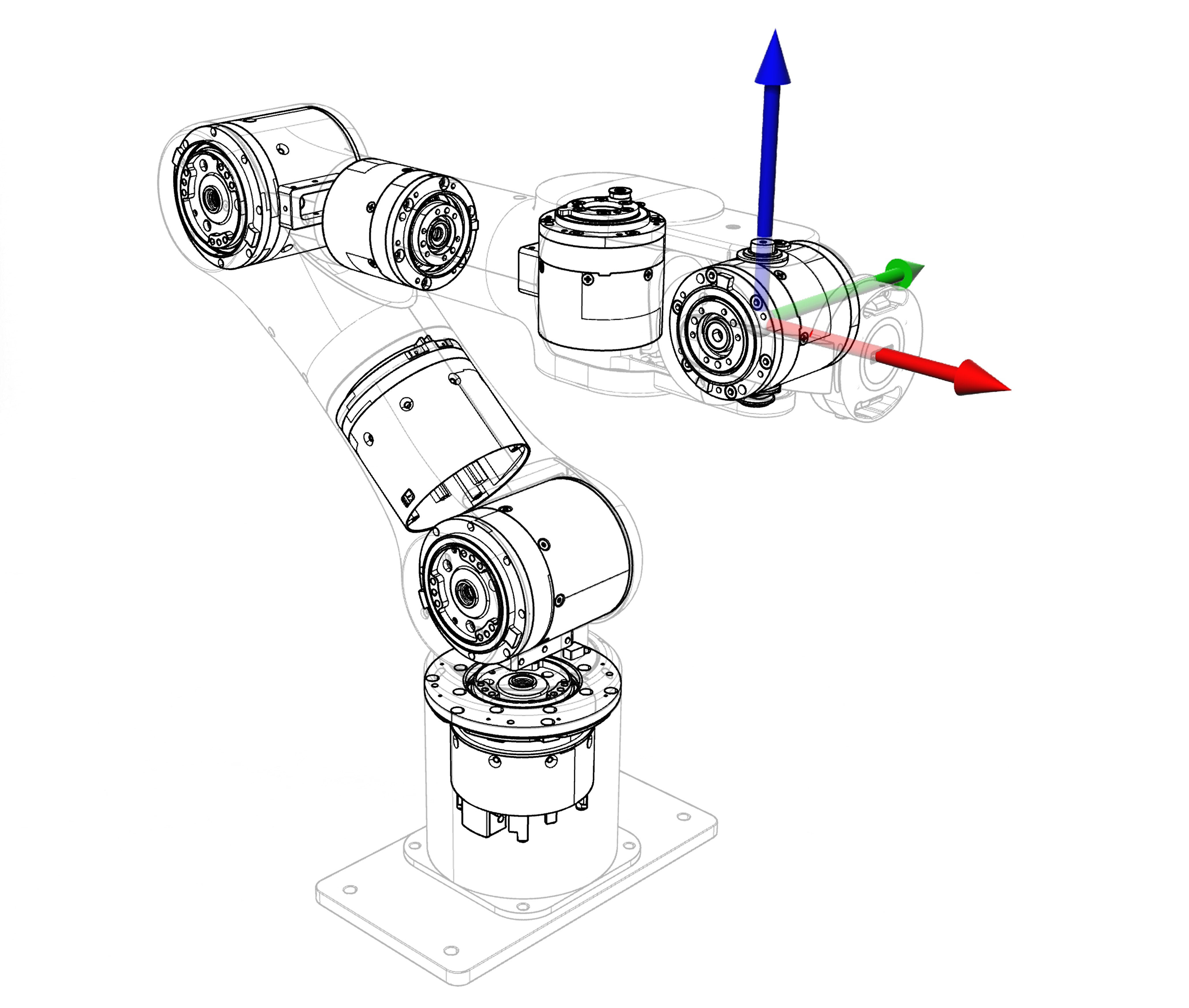
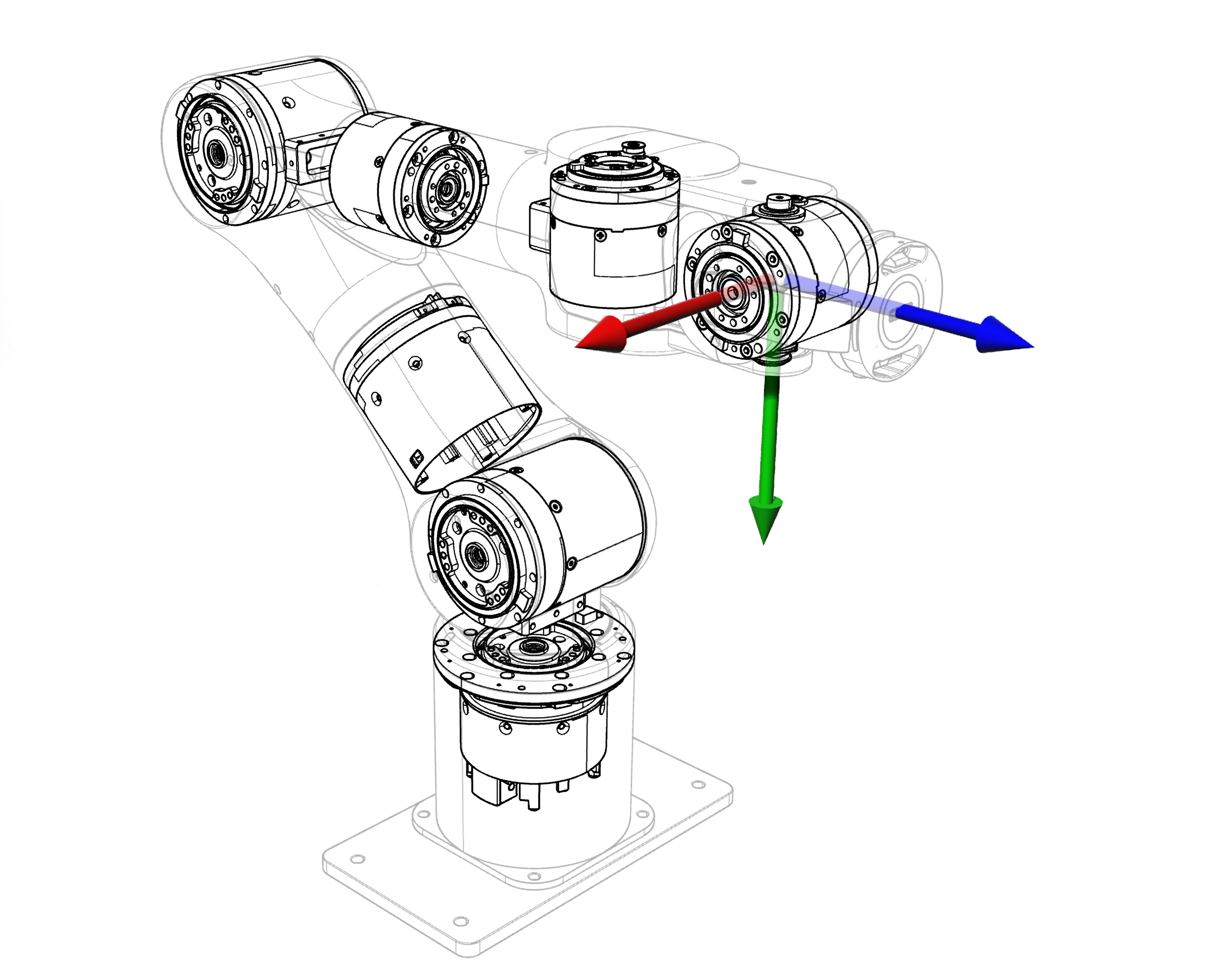
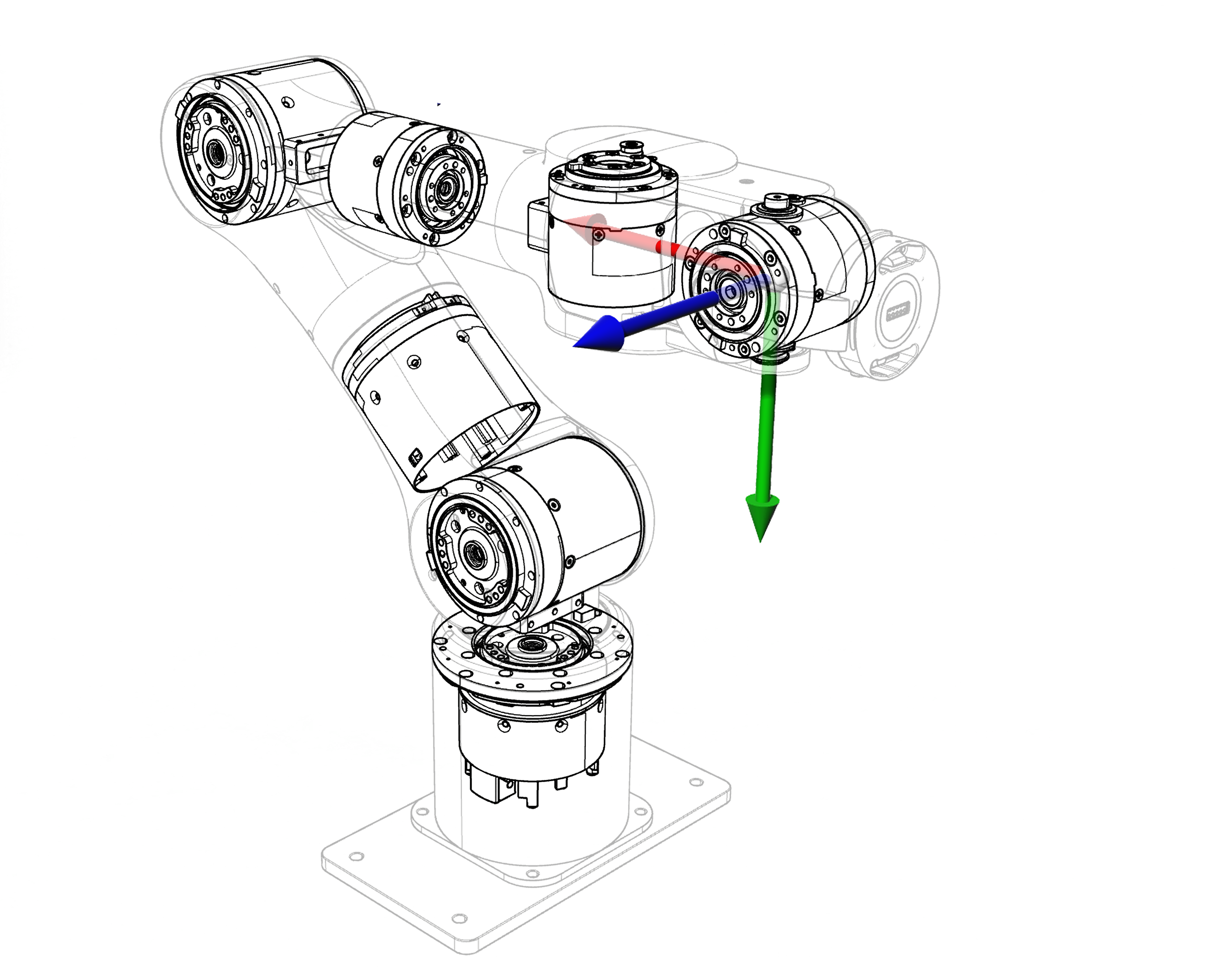
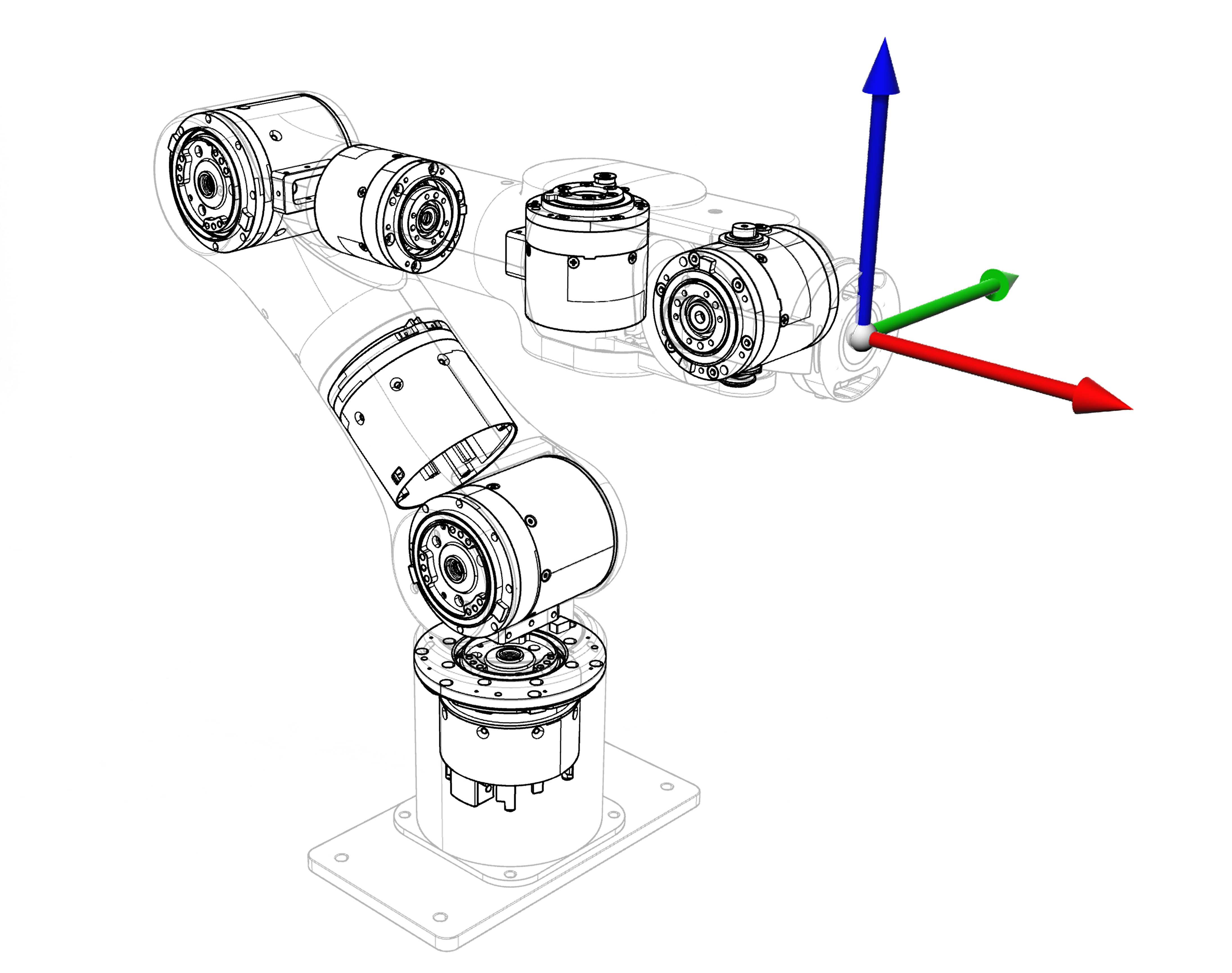
The AIRBOT P7 robot arm has 7 degrees of freedom and consists of J1-J7 joint motors.
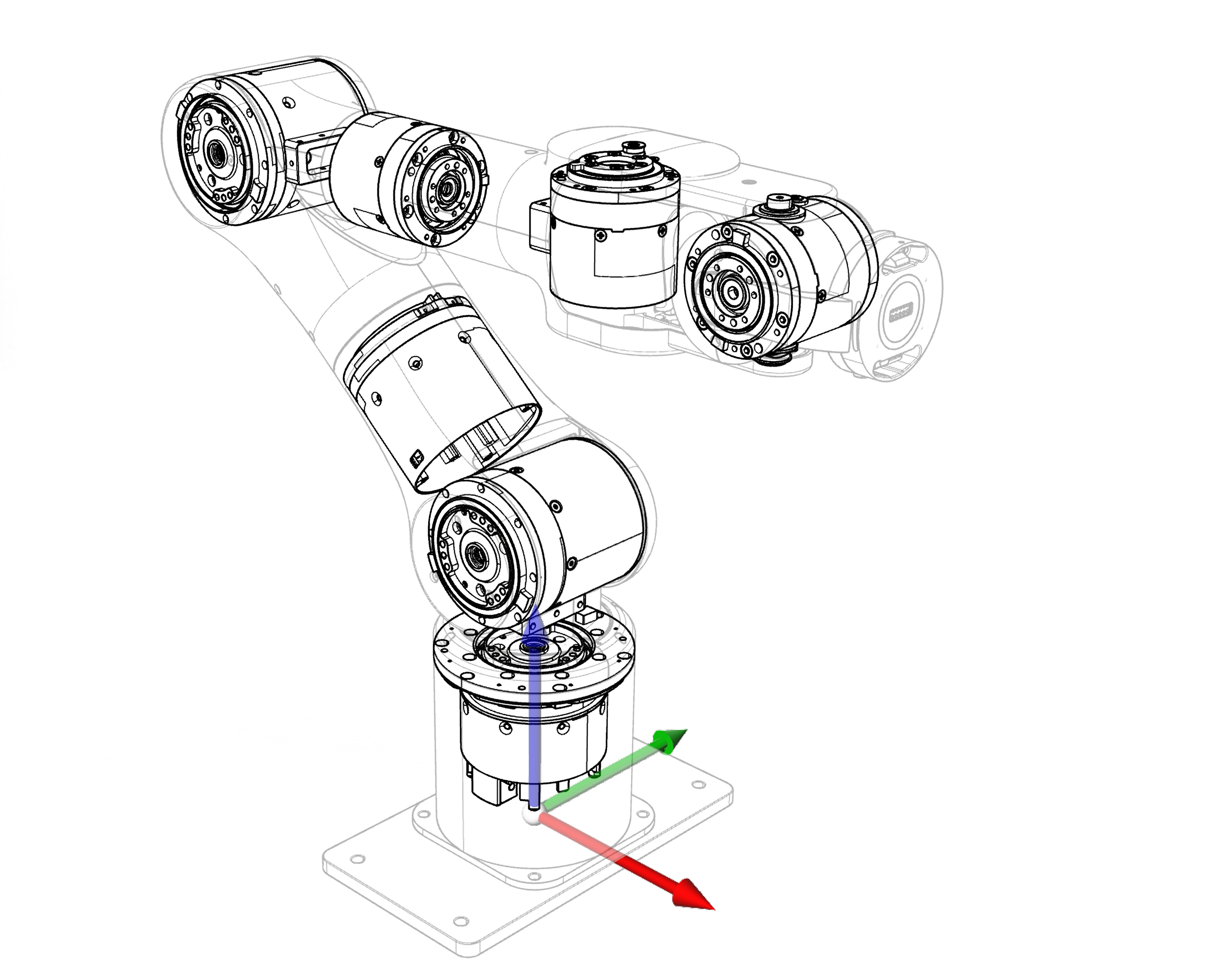
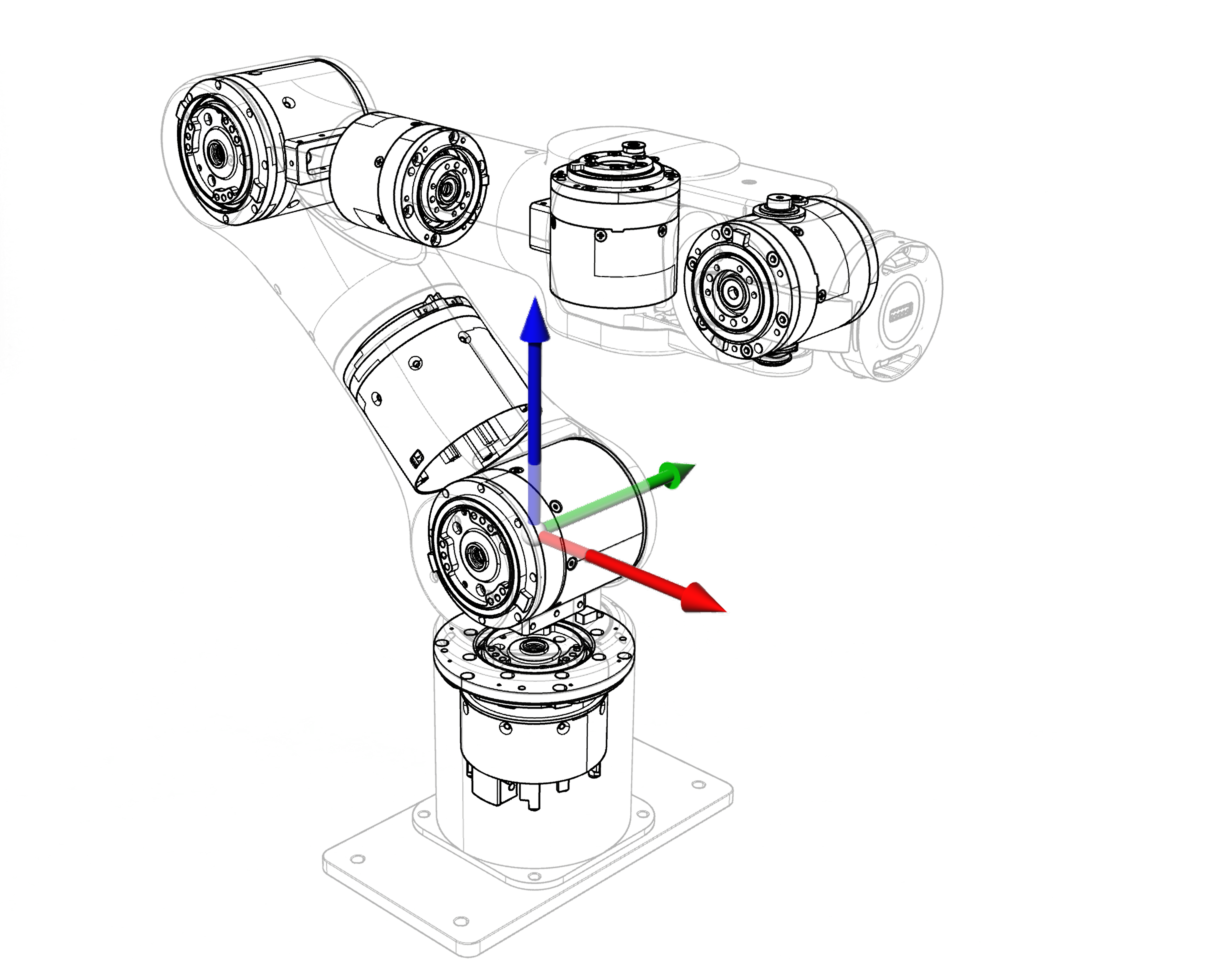
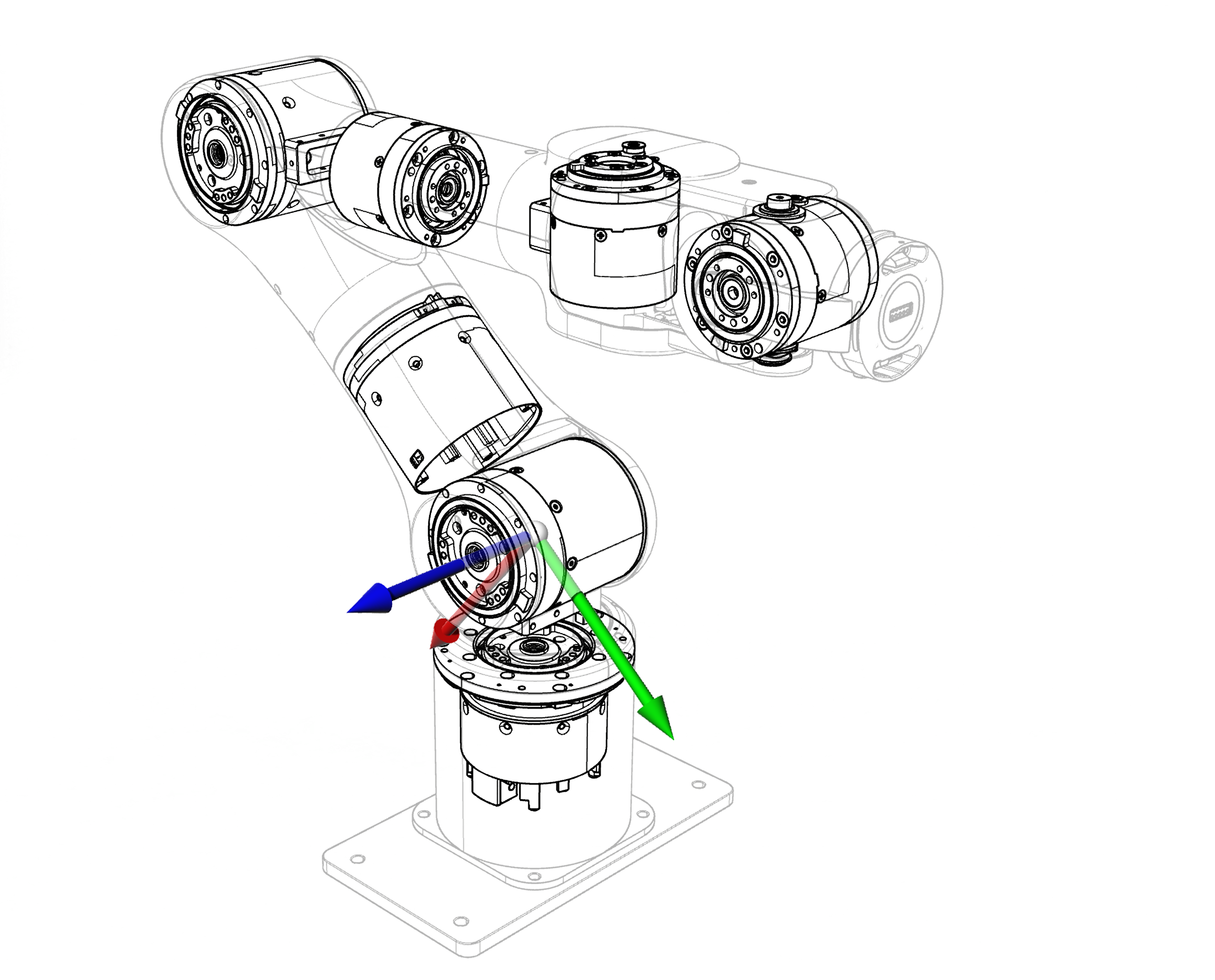
Each joint coordinate frame is defined using the right-hand rule. As shown in the image below, coordinate-axis colors are: X axis\—red, Y axis\—green, and Z axis\—blue. Each color direction indicates the positive direction of that axis.

Workspace#
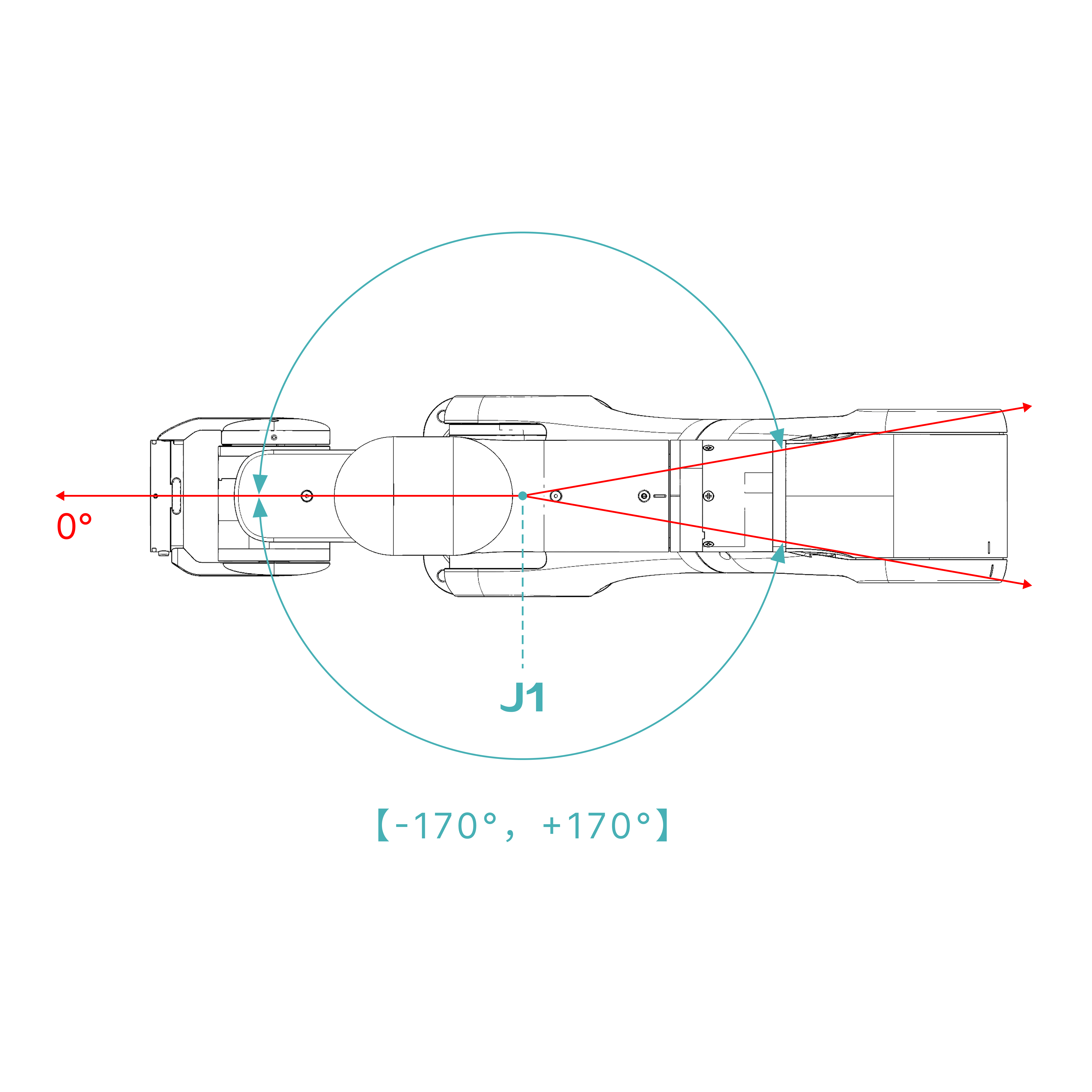
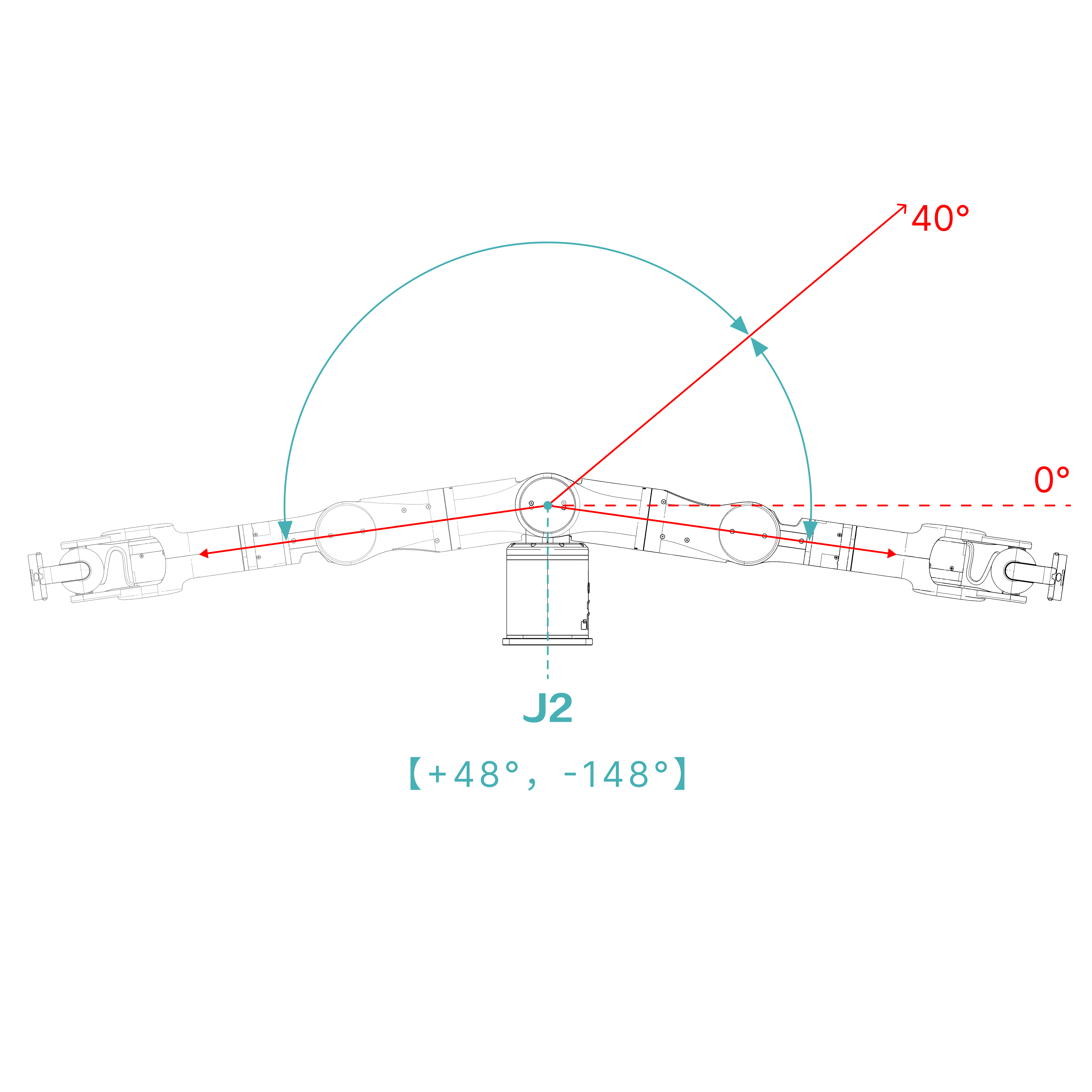
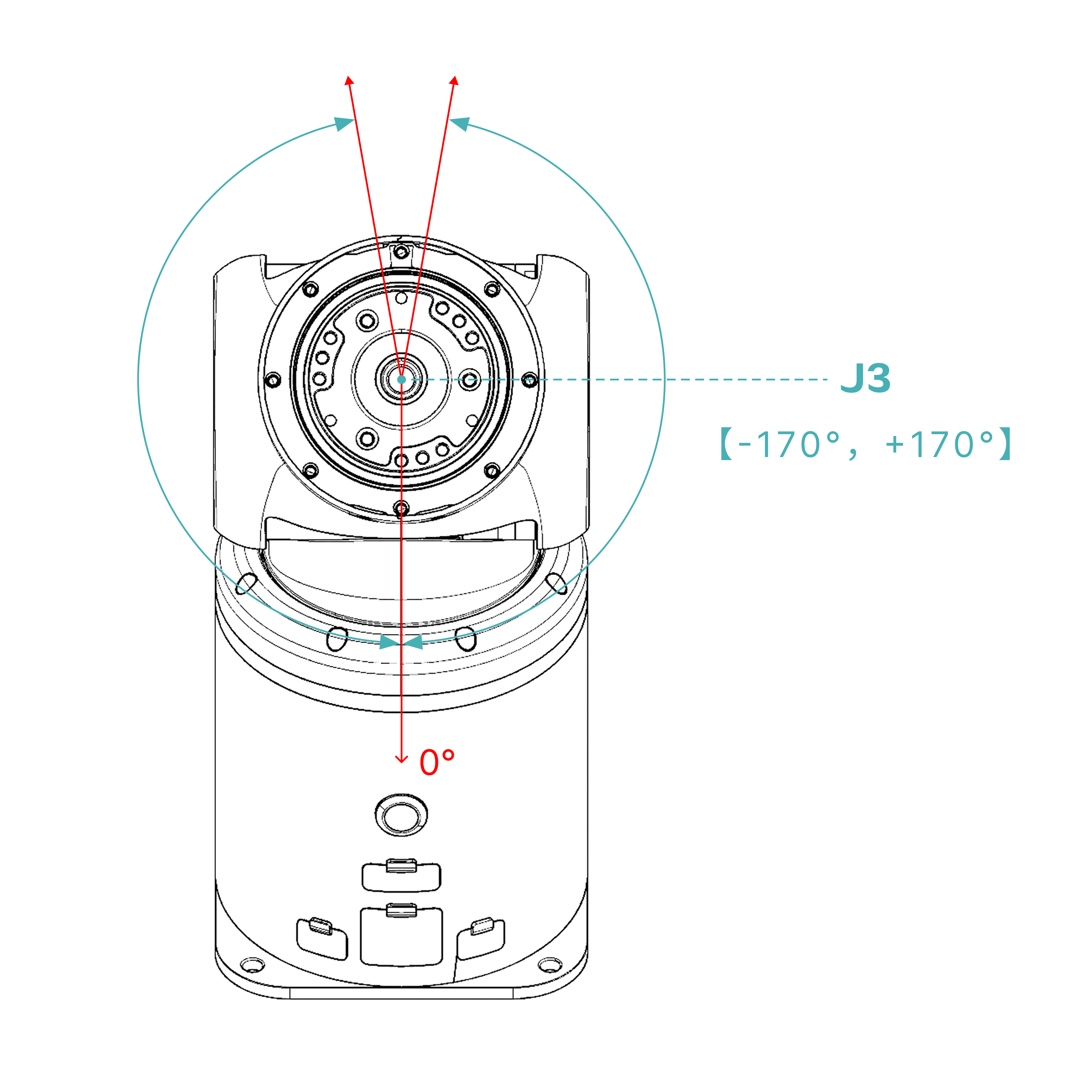
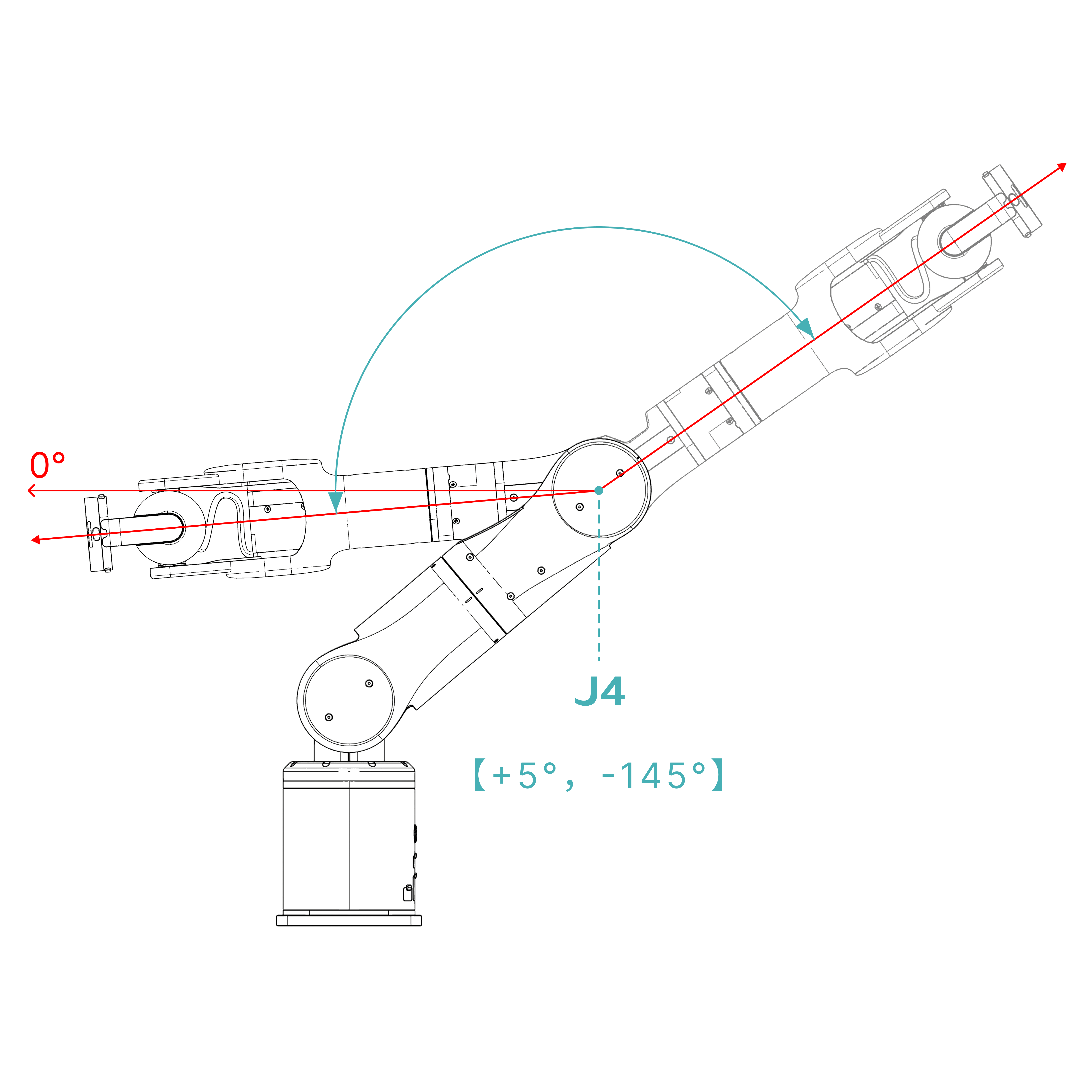
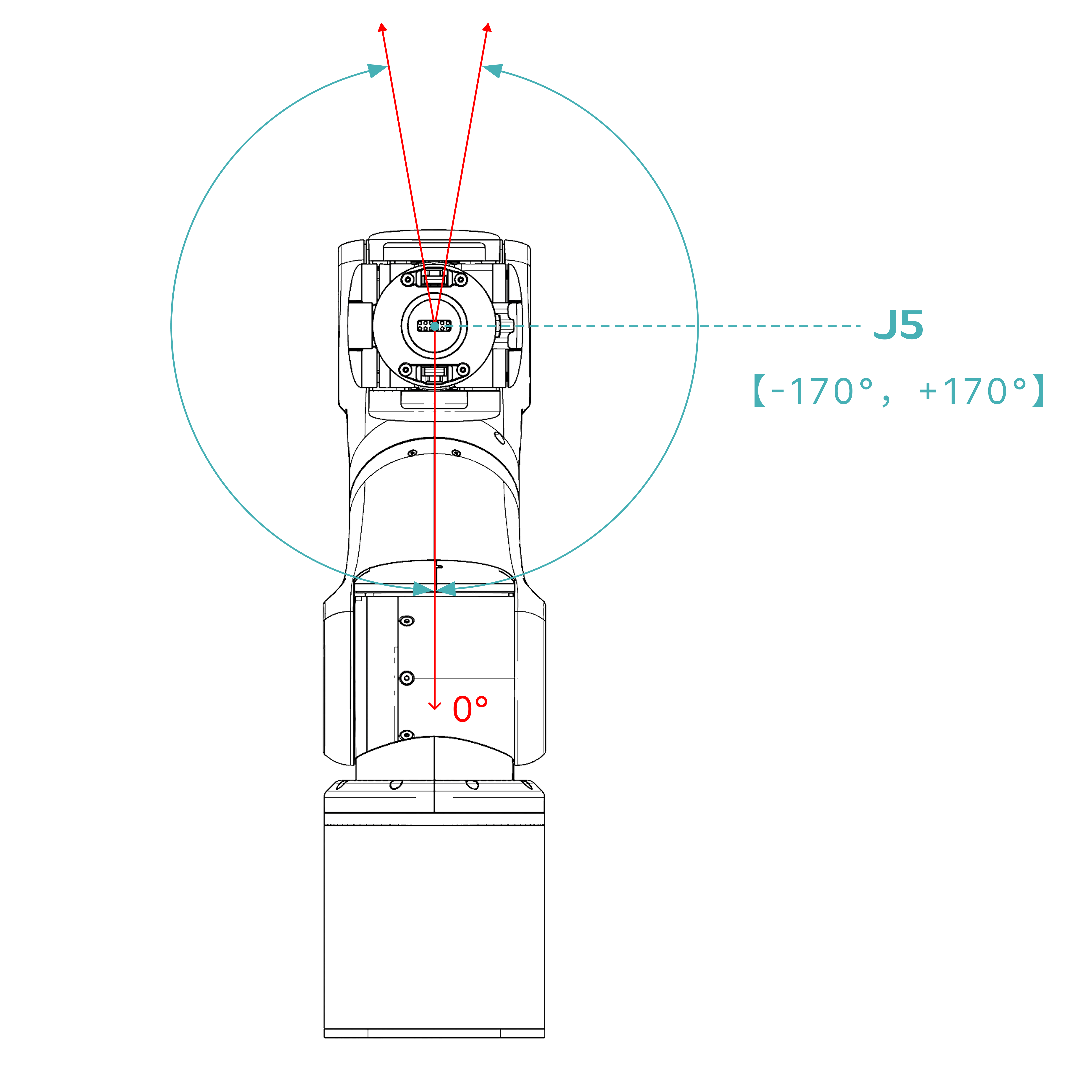
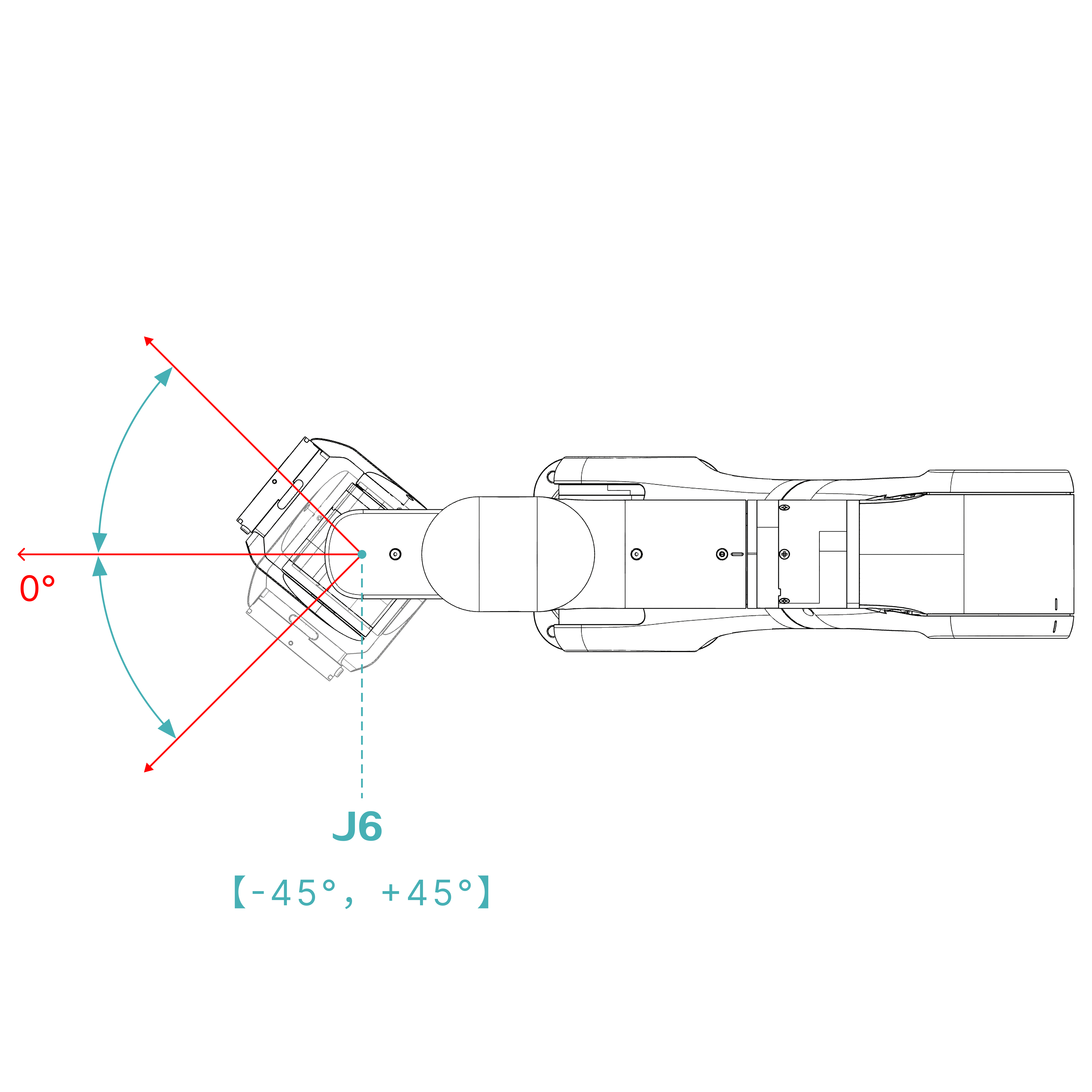
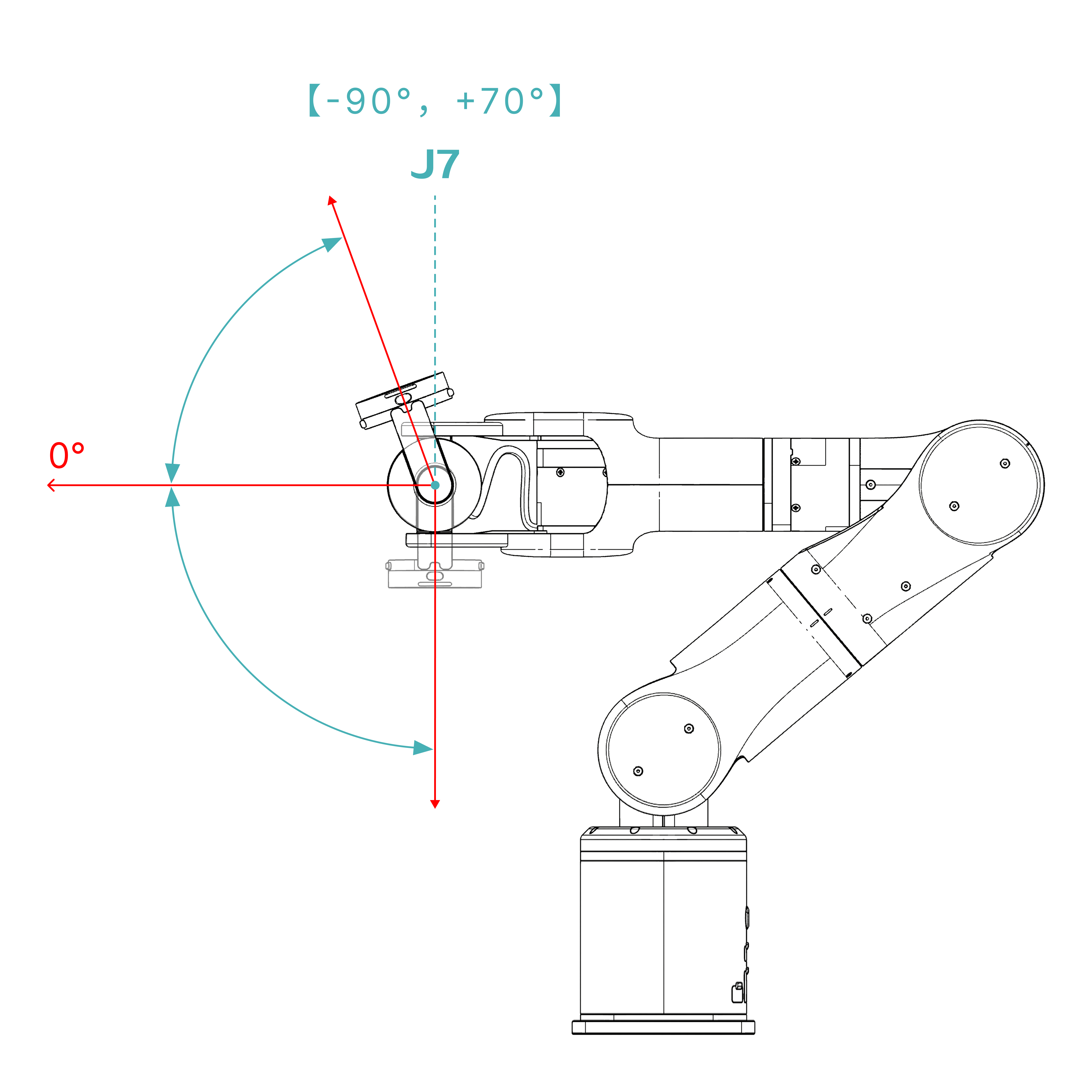
The AIRBOT P7 has a maximum working radius of 640 mm without an end effector. The diagrams below show the range of motion of each joint. Select an image to view it at full size.