User Manual
> Product Information
Hardware Interfaces#
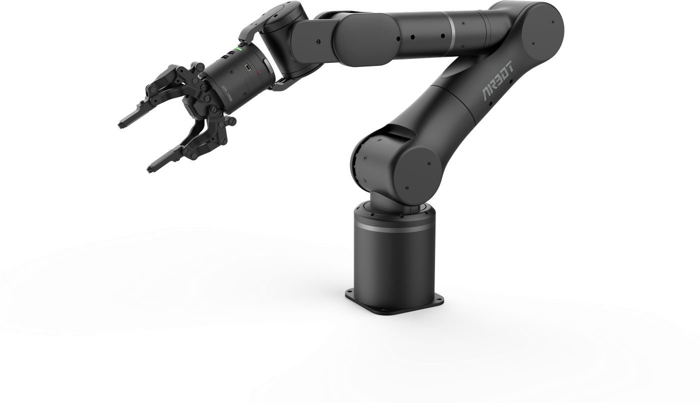
The AIRBOT P7 body interfaces are mainly located on the robot arm base and end.
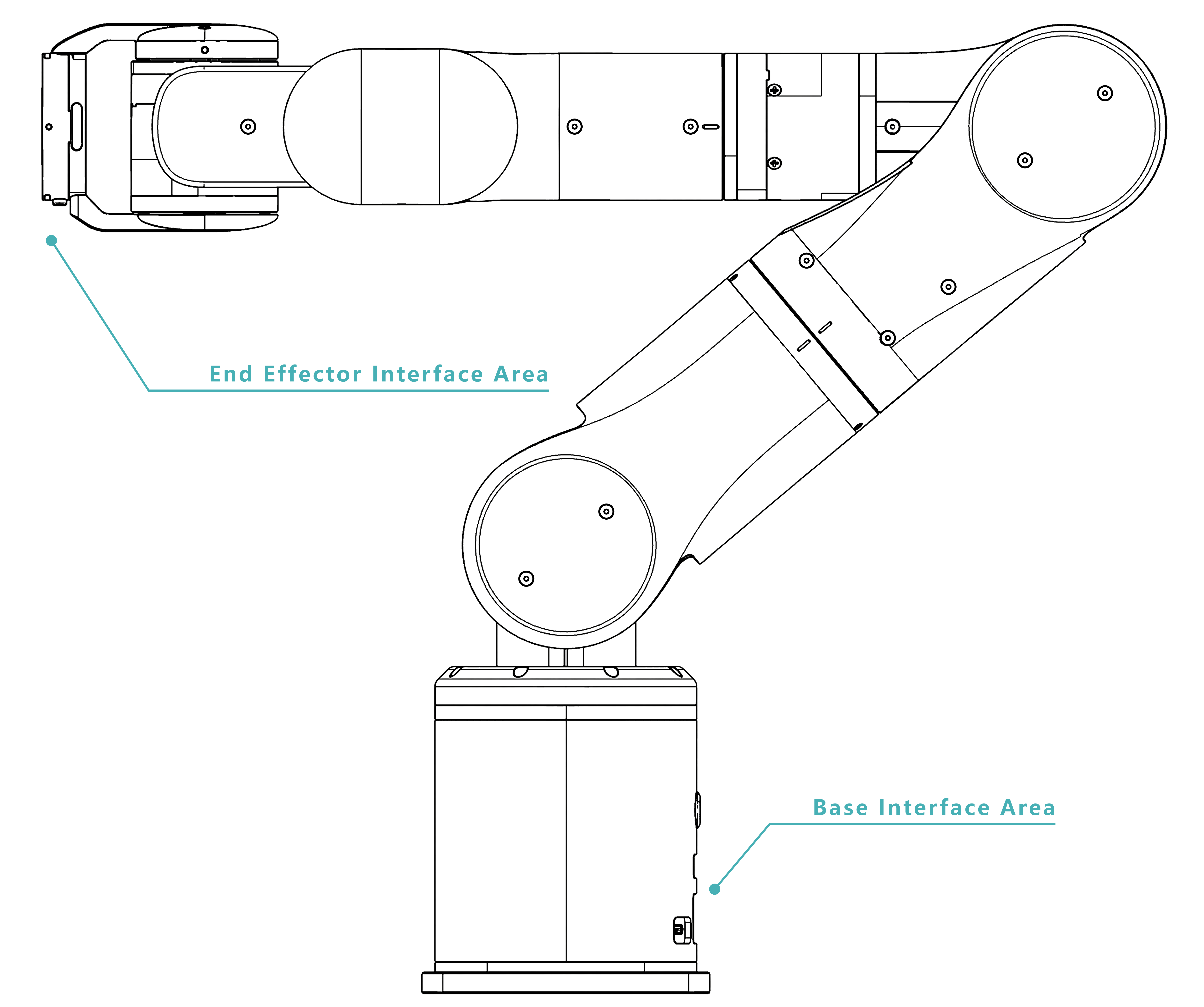
Base Interfaces#
All base interfaces are located on the base panel.
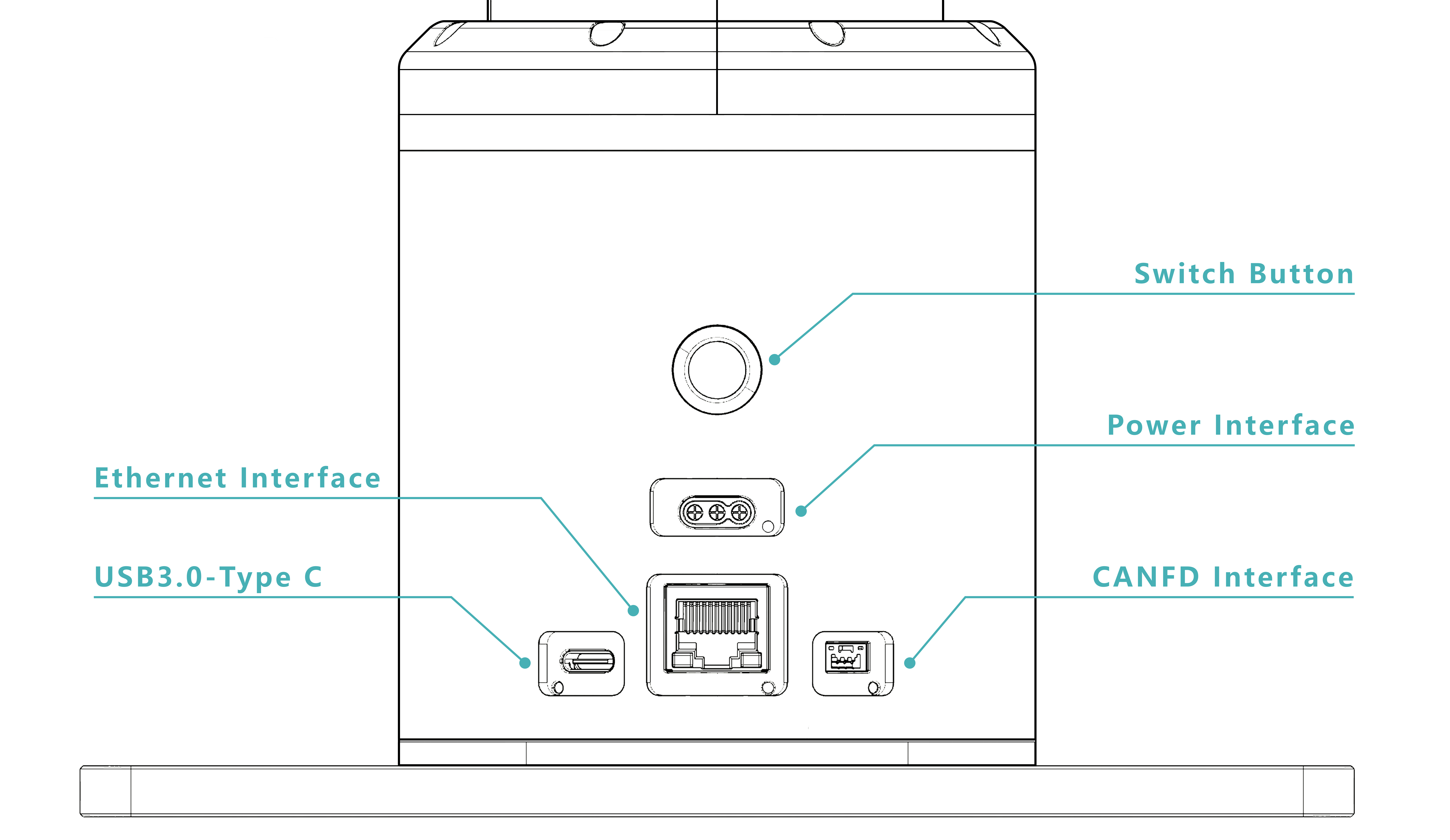
Power interface: connects the robot arm power cable through the 3-pin MR30-M connector output by the power adapter.
Signal interfaces:
- USB 3.0 Type-C interface: supports end-mounted cameras with a USB 3.0 interface and transfers camera data to the host computer.
- Ethernet interface: communicates with the X5 chip and supports invoking the robot arm's preset motion modes and corresponding APIs.
- CANFD interface: intended for applications requiring higher control performance or custom motion-control algorithms.
Switch button: powers the robot arm on and off.
End Interfaces#
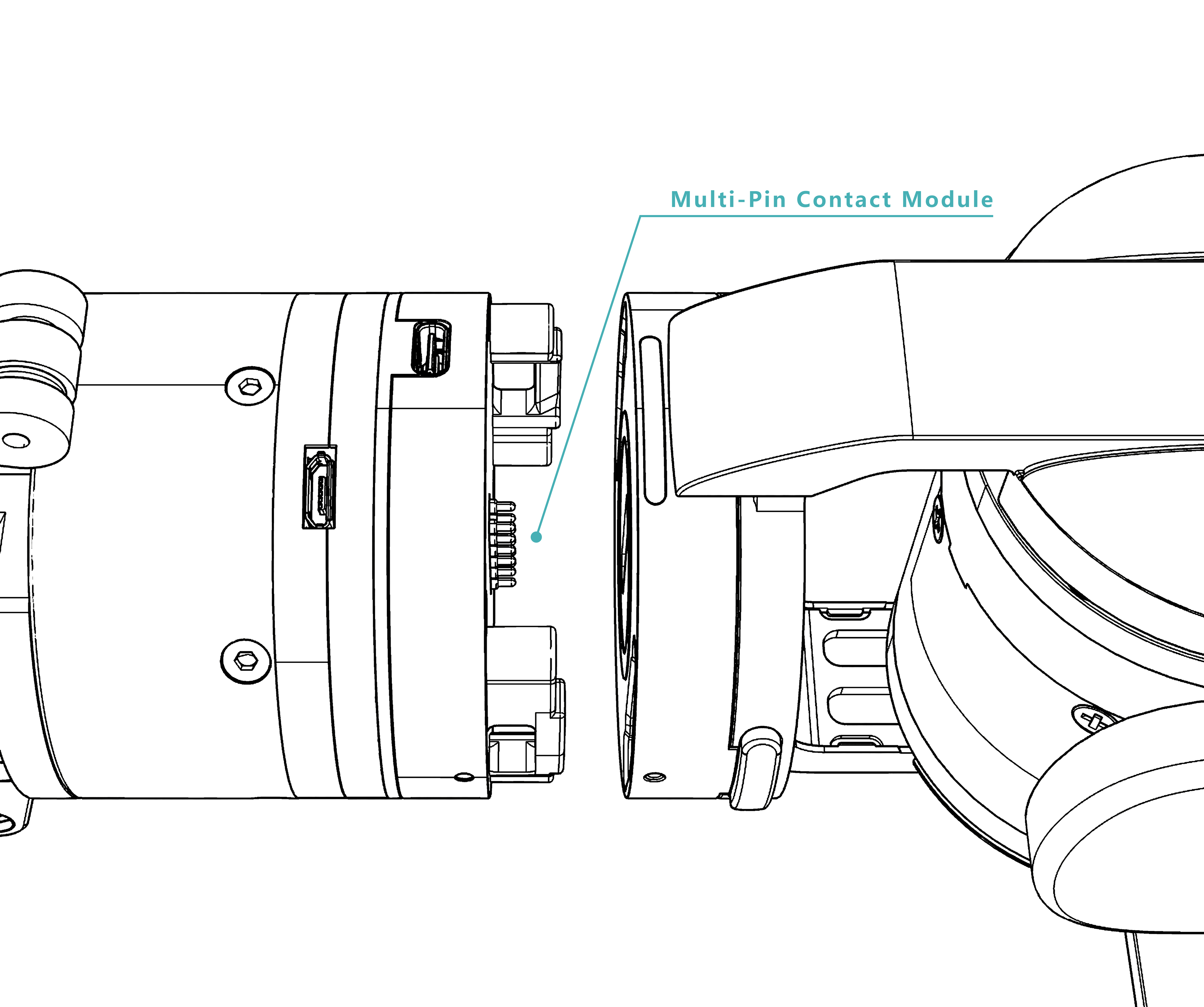
End interface: connects signals from end devices through a multi-pin contact module. Signals pass through internal robot-arm wiring to the base board. A quick-release structure keeps the appearance tidy and reduces interference from external wiring in the workspace.
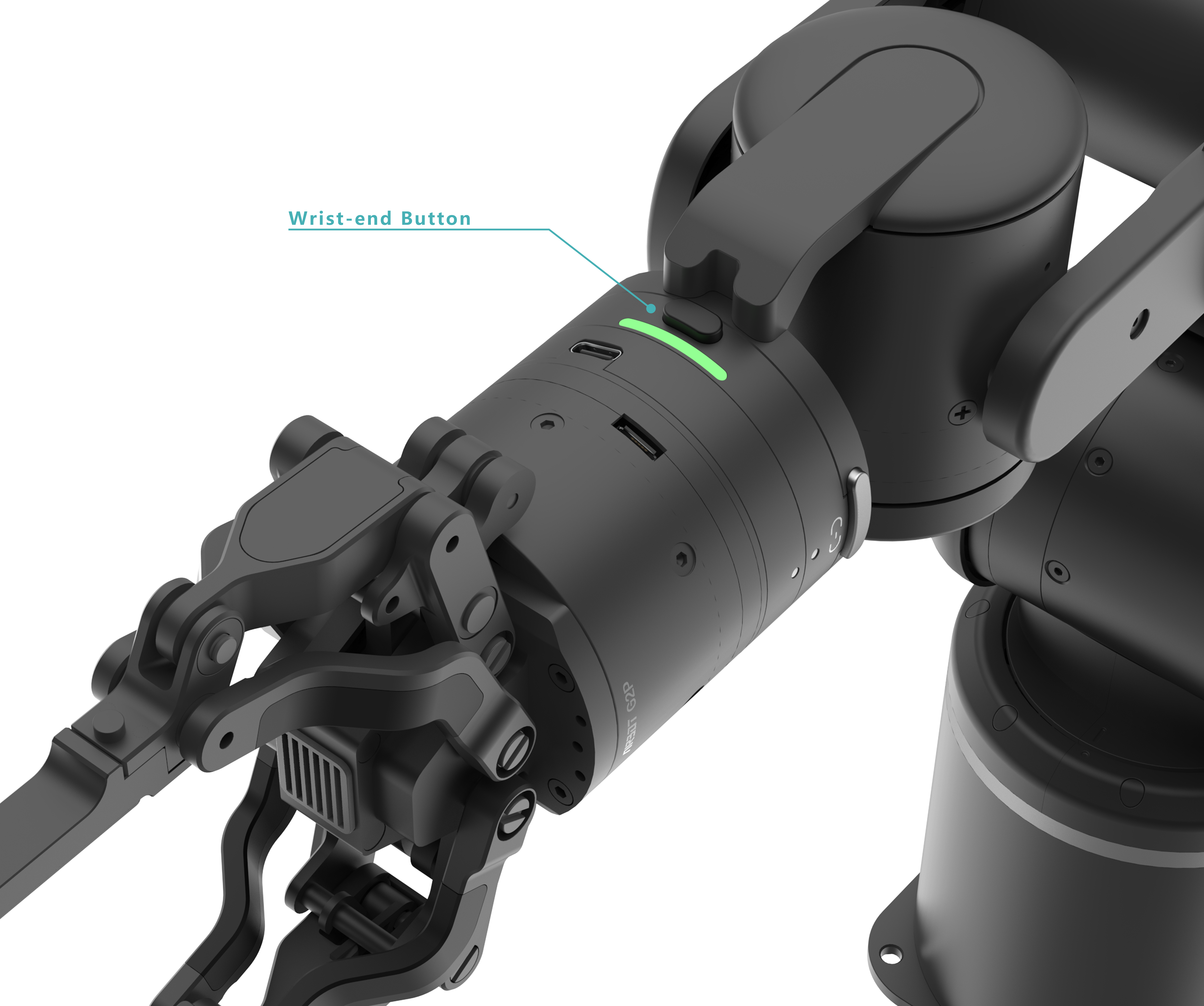
End button: switches the robot arm mode.