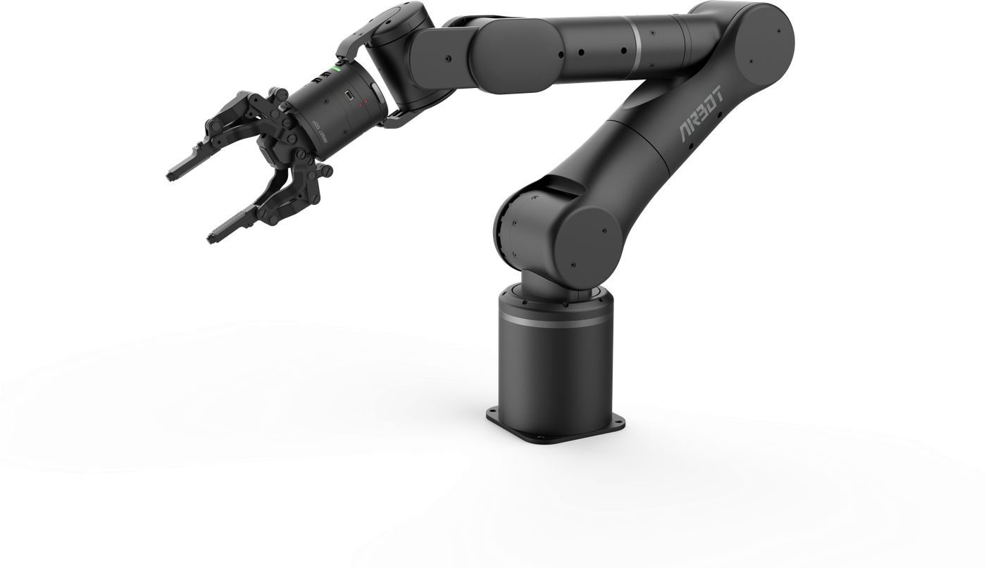
User Manual
> Hardware Installation
Base Connections#
The base-panel interfaces are shown below:
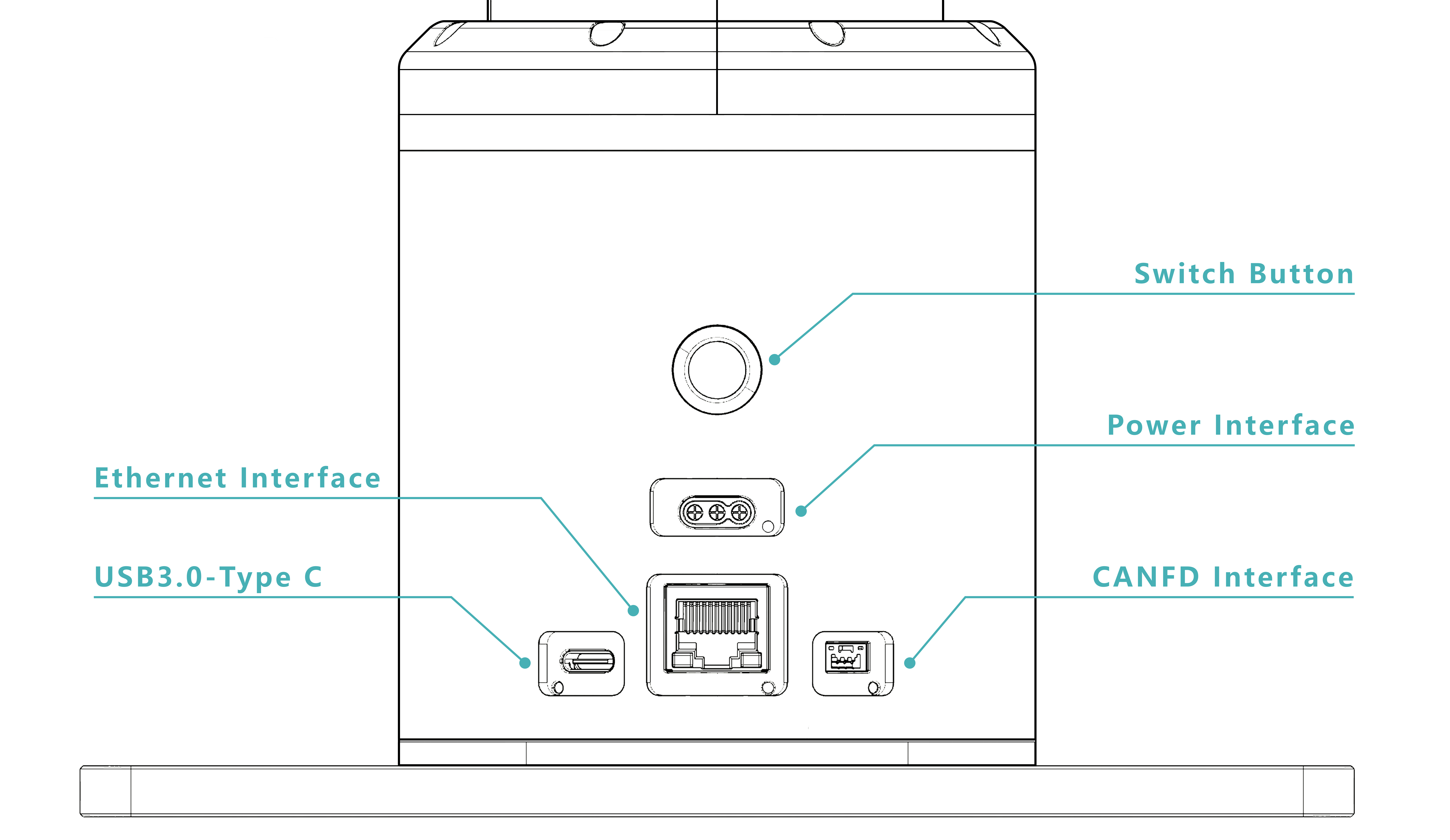
Switch button: controls the robot arm's power state. A white indicator means that power is on; an unlit indicator means that power is off.
Power interface: connects the robot arm power cable through the 3-pin MR30-M plug output by the power adapter.
USB 3.0 Type-C (camera interface): supports end-mounted cameras with a USB 3.0 interface and transfers camera data to the host computer.
Ethernet (X5 interface): communicates with the X5 chip and supports invoking preset robot-arm motion modes and corresponding API interfaces.
CANFD interface: for customers who require higher control performance or custom motion-control algorithms.