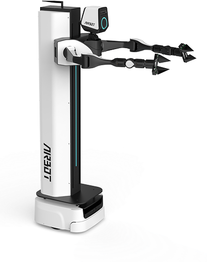
▸ Quick Start
Unpacking and Installation#
Package Contents#
Before starting, make sure that the packages contain all required components.
📦 Before Unpacking#
You will receive the following 4 separately packaged parcels:
- Robot main-unit wooden crate × 1 The wooden crate and packing inserts are reusable. Store them safely.
- Standard-accessories carton × 1
- Teaching-backpack carton × 1 (optional)
- Backpack-stand kit × 1 (optional) This parcel consists of multiple component boxes strapped together.
🔧 Detailed Contents After Unpacking#
✅ Tip: Check each item carefully and make sure that all accessories are present.
| Package | Item | Quantity | Notes |
|---|---|---|---|
| Robot main-unit wooden crate | Robot main unit | 1 | Core equipment |
| Remote controller | 1 | ||
| Standard-accessories carton | Main-unit charger | 1 | |
| Base charging dock | 1 | ||
| Three-pin power cable | 1 | For the base charging dock | |
| Backpack carton (optional) | Teaching backpack | 1 | |
| Product document pouch | 1 | Includes: • MMK2 shipping checklist × 1 • MMK2 factory inspection report × 1 • Teaching-backpack factory inspection report × 1 • Teaching-backpack installation manual × 1 • Teaching-backpack stand installation instructions × 1 • Delivery receipt × 1 |
|
| Backpack-stand kit (optional) | Main stand | 1 set | |
| Backpack connector 1 | 1 set | Includes: • M4×4mm screws × 4 • M4×10mm screws × 4 • L-shaped wrench × 1 |
|
| Backpack connector 2 | 1 set |
Hardware Interfaces#
Rear Buttons and Interfaces#
| Function | Operation | Status Indication | Interface Image |
|---|---|---|---|
| Base emergency stop | Press: Immediately stops the base and locks the wheel hubs Release: Resumes normal operation |
Wheel hubs locked/released |  |
| Base brake | Press: Releases the brake so the robot can be pushed freely (make sure the emergency stop is released) Release: Applies the brake |
Movable/locked | 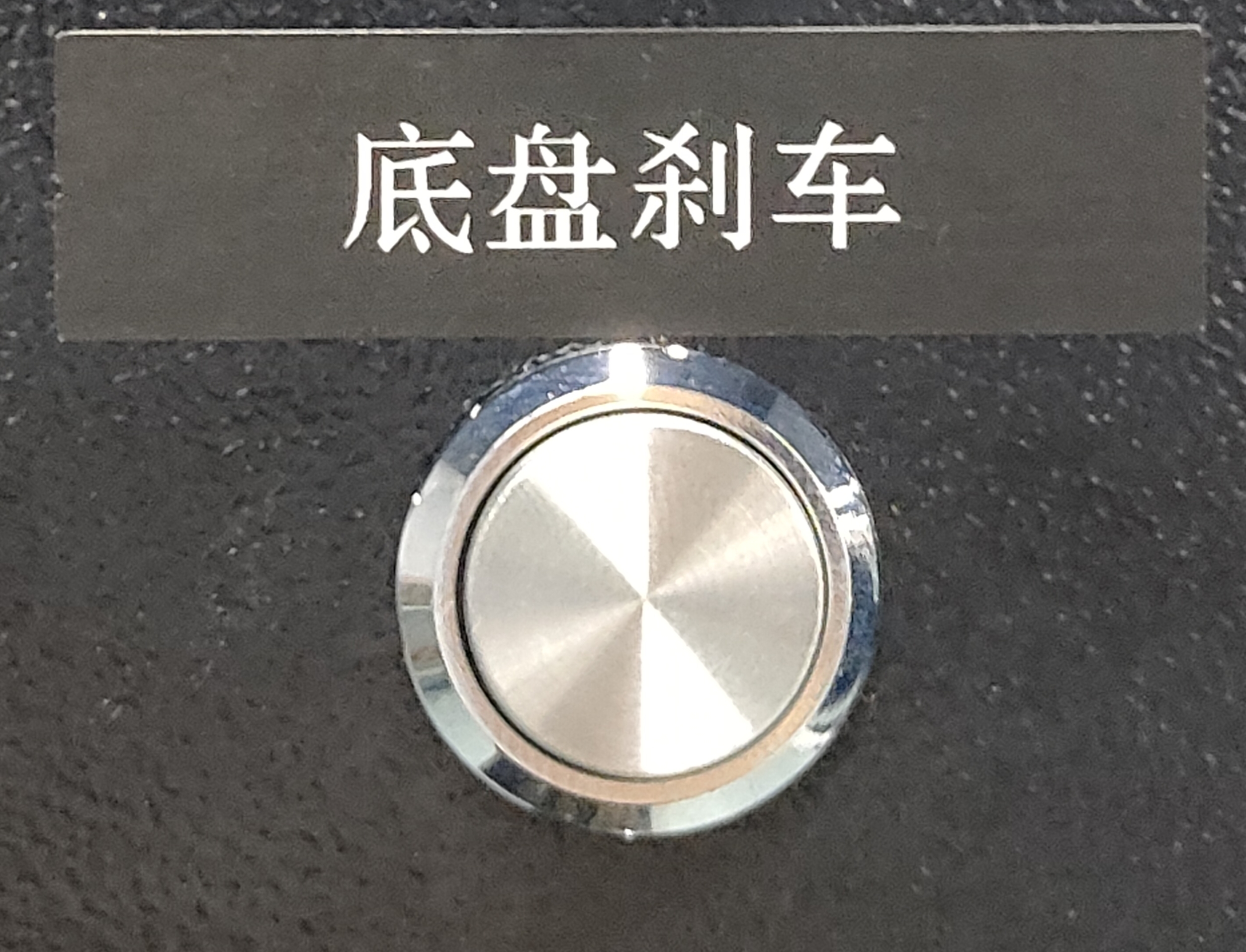 |
| Base power | Power on: Briefly press; base power turns on automatically while charging Power off: Press and hold until the indicator turns off |
Base indicator on/off | 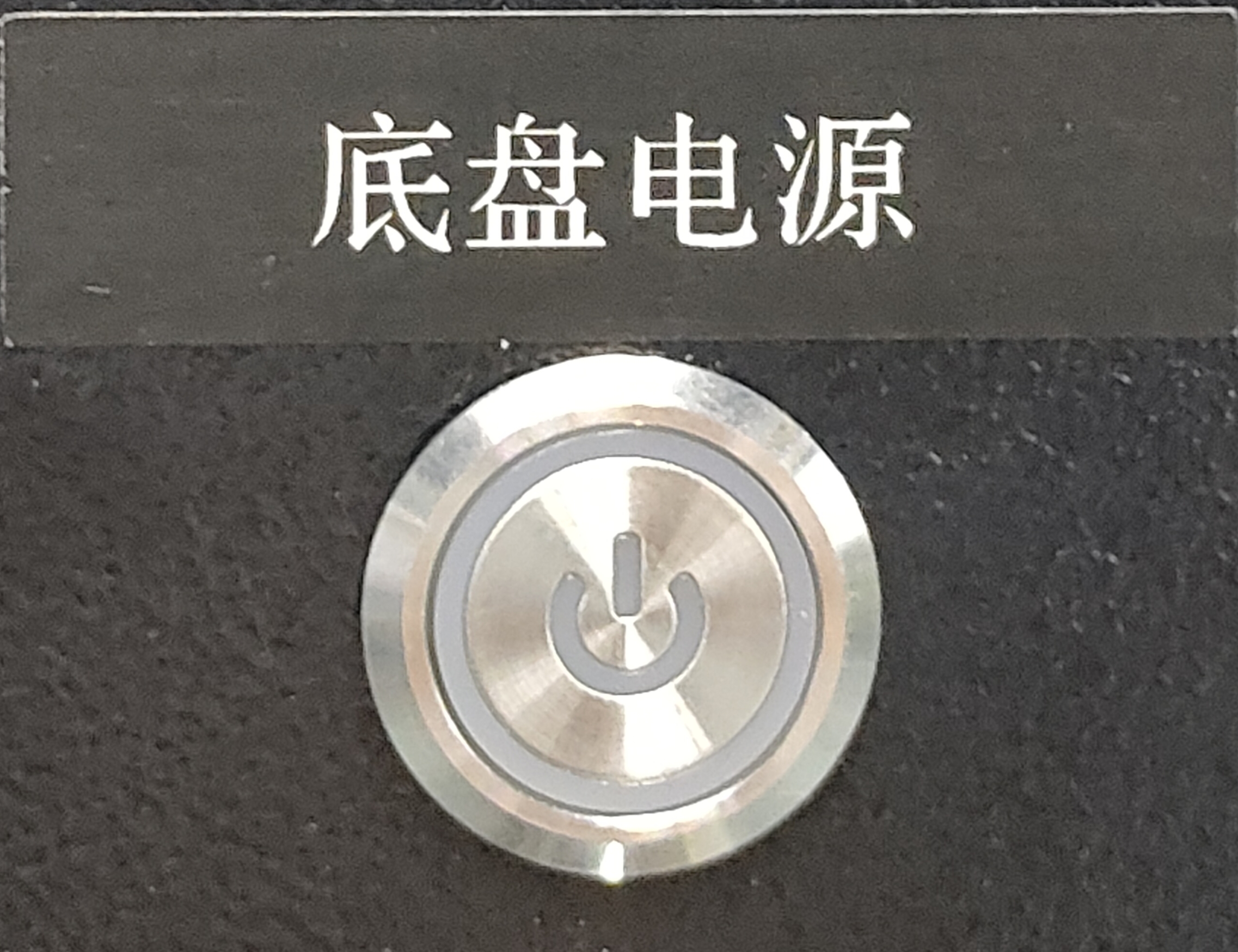 |
| Main-unit power | Power on: Press the switch Power off: Release the switch |
Head and body light strips on/off | 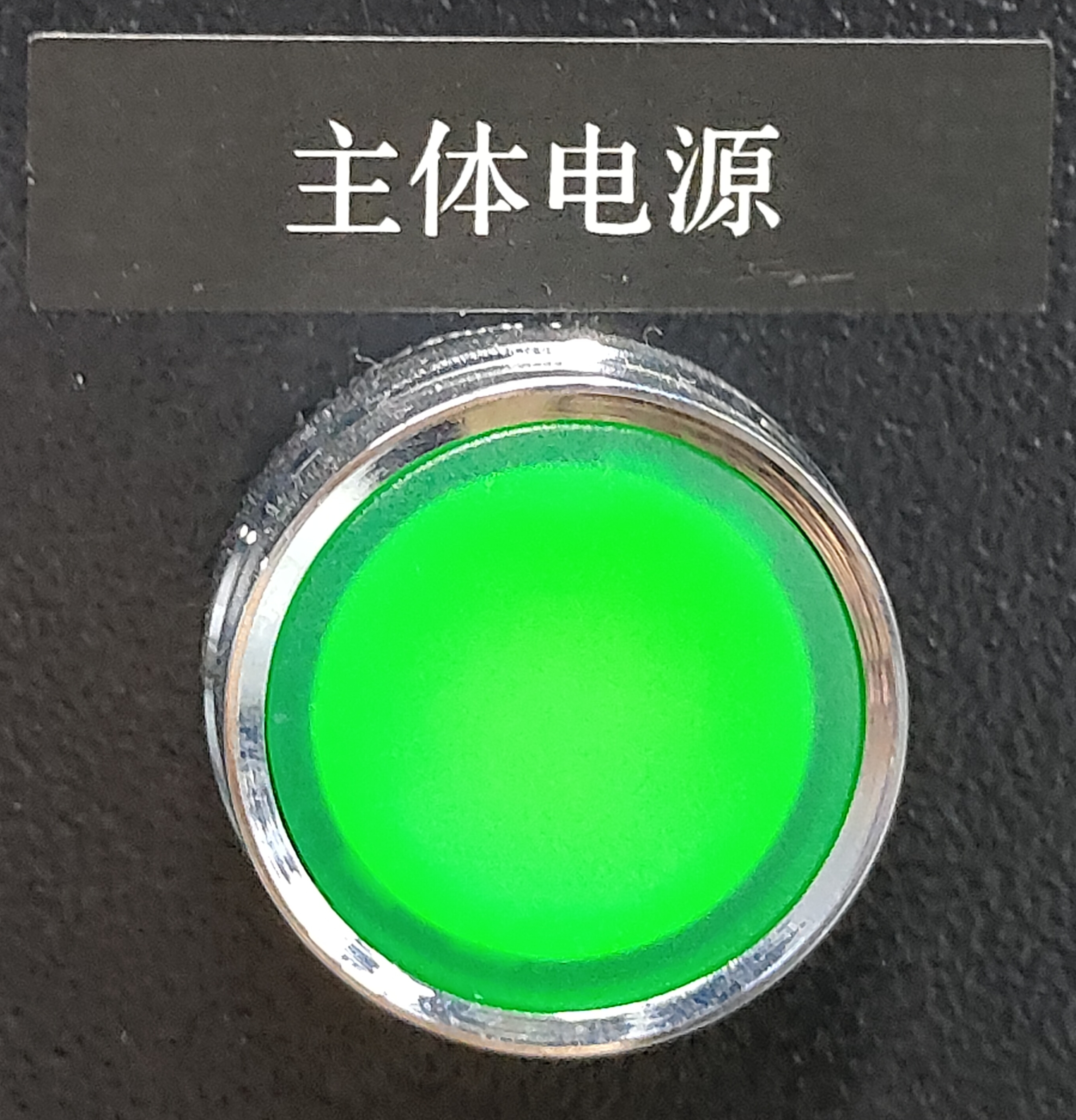 |
| Main-unit battery display | Press the white dot to cycle through: battery level → voltage → screen off | Audible low-battery (20%) alarm | 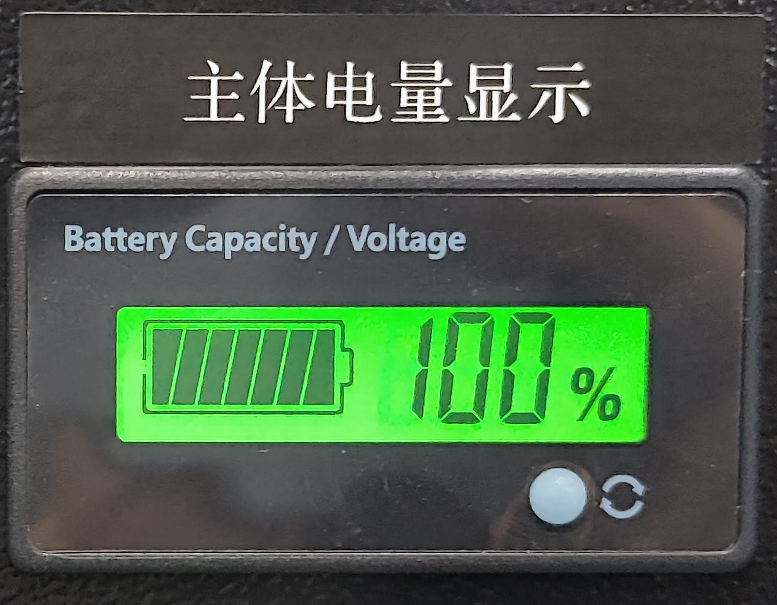 |
| Main-unit charging port | Connect the dedicated charger | 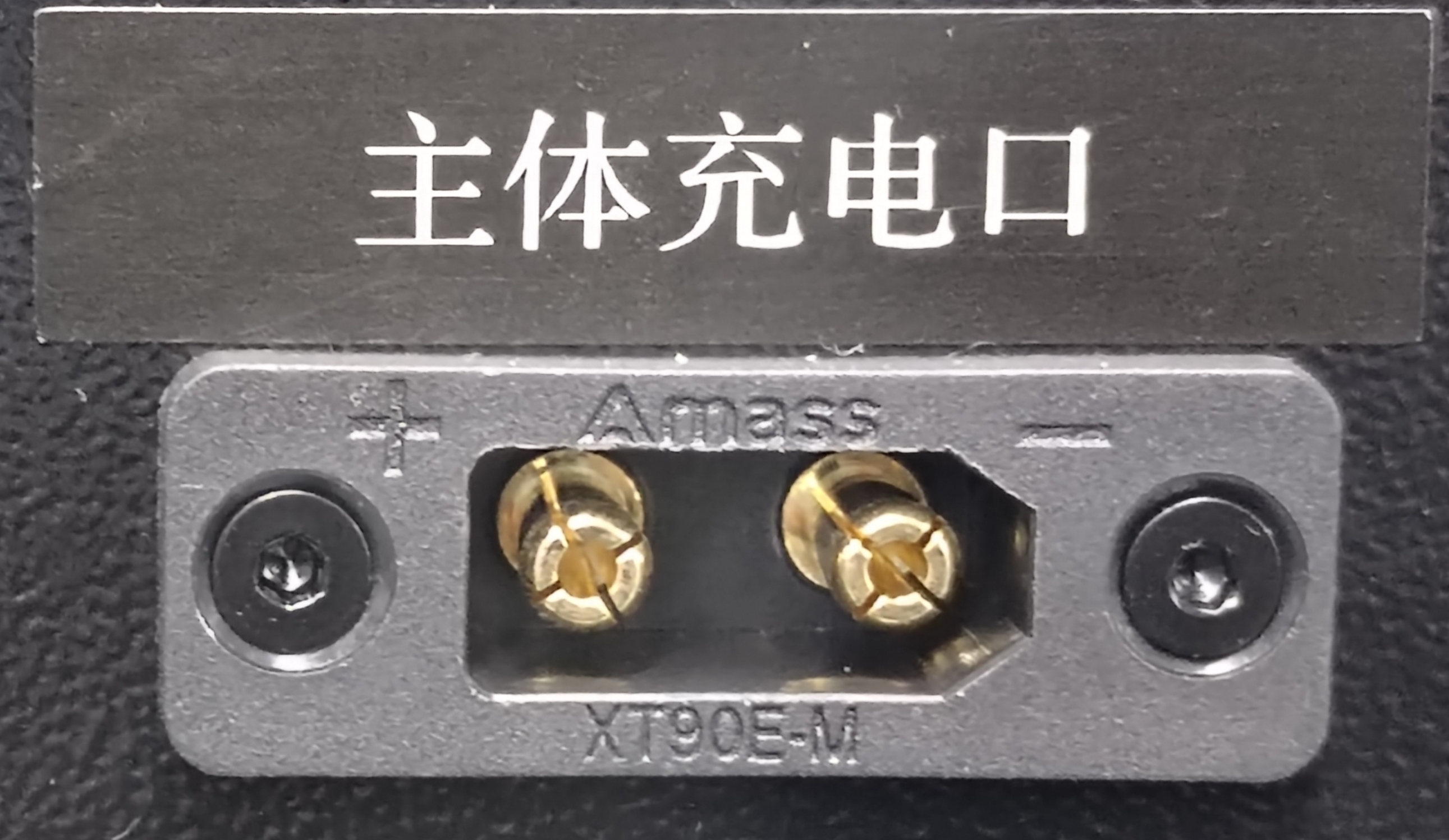 |
Robotic-Arm Base Interfaces#
Interface Layout#
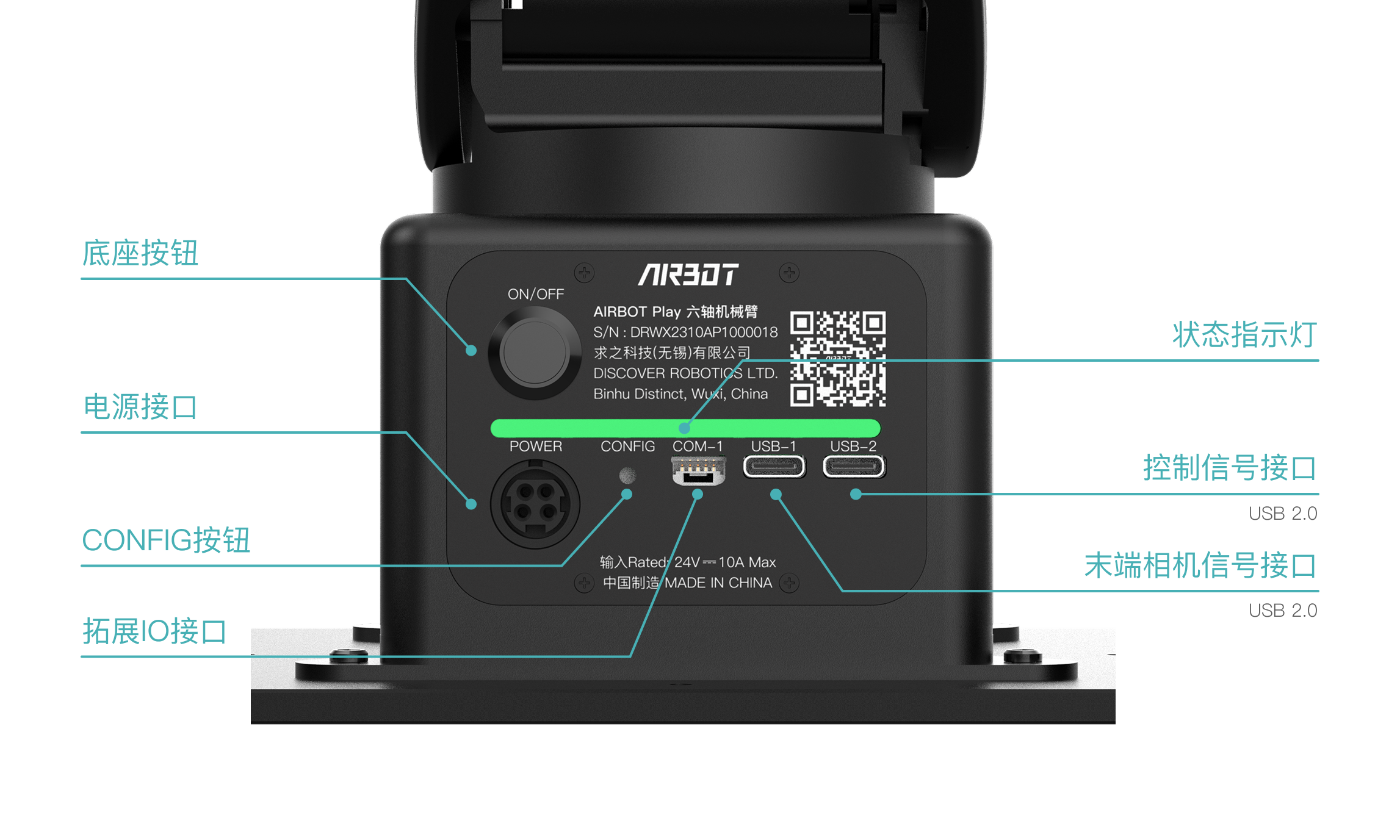
① Power connector ② Base button ③ USB-2 ④ USB-1
Interface Functions#
| Interface/Button | Primary Function | Key Information |
|---|---|---|
| ① Power connector | Powers the robotic arm | • Make sure the connection is secure • Insert the aviation connector with its black end (arrow marking) facing inward |
| ② Base button | Zero-position calibration | When the base light strip flashes yellow: • Press and hold: Starts calibration • Briefly press: Ends calibration |
| ③ USB-2 (Type-C) | Robotic-arm control signal | Connects to the main controller In an emergency, disconnect this connection to stop the robotic arm |
| ④ USB-1 (Type-C) | End-effector vision data transmission | The hand-camera signal is routed internally through the robotic arm and output from this interface to the main controller |