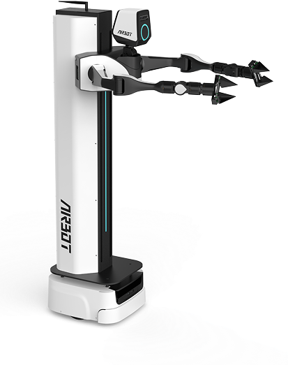
MMK2 Host-Computer UI Guide#
Open and Close the Application#
-
Open the user application
- Extract the archive and open the
mmk2_uifolder. - Double-click the
mmk2_uifile.Alternatively, open a terminal in the same directory and run:
- Extract the archive and open the
-
Close the user application
-
In the UI, click x, and then click Yes.
-
In the terminal, press Ctrl + \.
-
Use the User Interface#
Interface Overview and Functions#
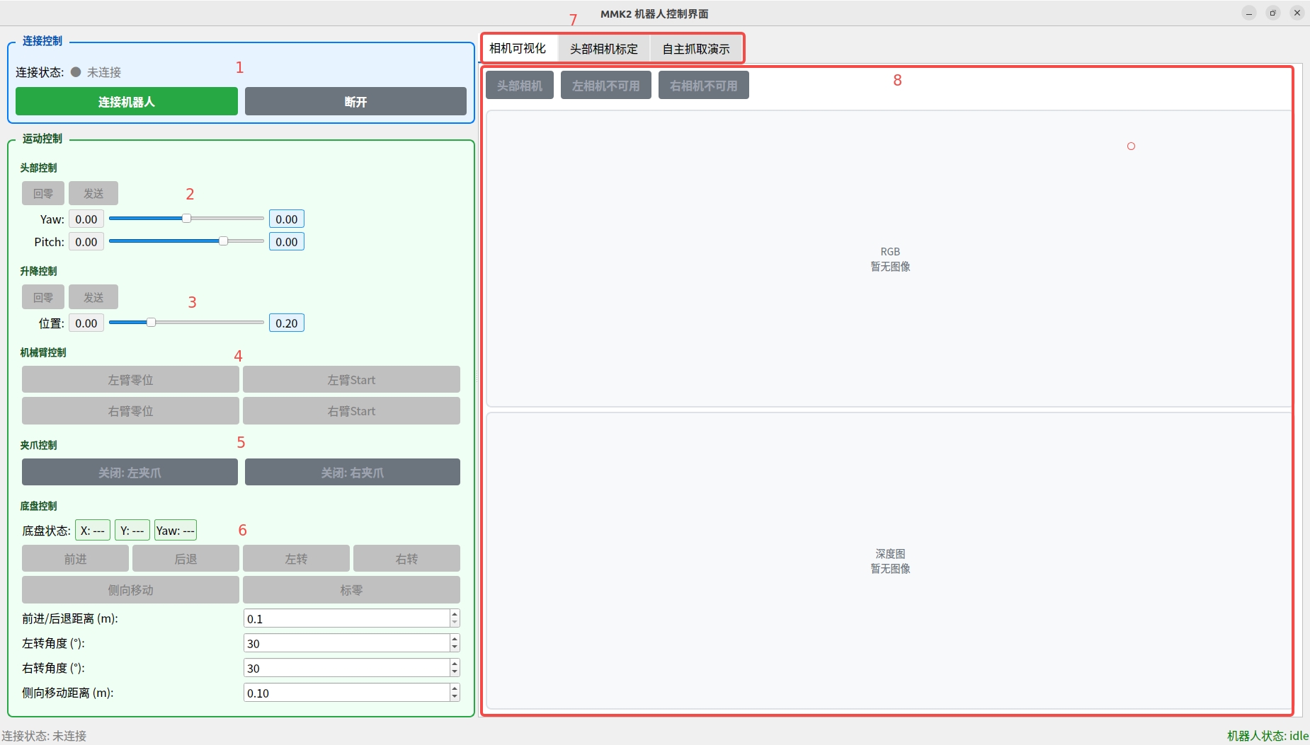
Host-computer main interface
| Module | Function | Description |
|---|---|---|
| 1 | MMK2 communication module | Device connection and status monitoring |
| 2 | MMK2 head control module | Head motion and vision control |
| 3 | MMK2 spine lifting control module | Body-height adjustment |
| 4 | MMK2 robotic-arm motion control module | Dual-arm trajectory planning and control |
| 5 | MMK2 robotic-arm gripper control module | Gripper opening and closing |
| 6 | MMK2 base control module | Mobile-base motion control |
| 7 | MMK2 function module | Visualization, camera calibration, and demos |
| 8 | Function implementation area | Command execution and status feedback |
Recommendations
- Full-screen mode is recommended for the best operating experience.
- Some functional areas may be hidden when the window is too narrow.
- A screen resolution of at least 1920×1080 is recommended.
Function Modules#
MMK2 Communication Module#
Overview: This module provides the MMK2 robot connection-management interface and supports wired and wireless connections:
- Wired: Default IP
192.168.11.200 - Wireless: See Wireless Connection for instructions on obtaining the IP address.
RealSense camera serial-number lookup:

# 1. Test the wired connection
ping 192.168.11.200

# 2. Log in remotely; password: airbot
ssh orangepi@192.168.11.200

# 3. Check the camera serial number
docker exec -it airbot_mmk2_1.1.3 bash  # airbot_mmk2_1.1.3 is the running container name
rs-enumerate-devices | grep Serial

# 4. Restart the container (required after querying the SN)
docker restart airbot_mmk2_1.1.3  # Exit the container, and then run this on the Orange Pi
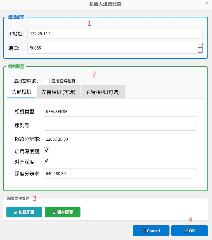
Connection configuration
Procedure:
-
Enter the destination IP address and port (default: 50055).
-
Select the camera types to enable and their parameters. For a RealSense camera, enter the corresponding device serial number.
-
You can save the current configuration and load it later to restore the parameters.
-
Click OK to open the home page. The connection status changes to Connected.
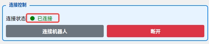
Connection status
- Click Disconnect to disconnect from the MMK2.
Head Control Module#
Overview: This module provides manual adjustment of the head pose and precise control of two rotational degrees of freedom:
- Yaw: Turns the head left and right.
- Pitch: Tilts the head up and down.
Parameter unit: radians
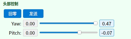
Head control
Important
- Before use, make sure that both robotic arms have moved to the Start position to prevent collisions.
- Actual position control may have an error of approximately ±0.01 meters.
Procedure:
-
Return the head to zero Click Zero. The head automatically returns to its preset zero position.
-
Adjust the pose Move the slider to the target position, and then click Send. The head moves precisely to the specified pose.
Spine Lifting Control Module#
Overview: This module precisely controls the MMK2 spine height and supports position adjustment and one-click return-to-zero.
Parameter unit: meters
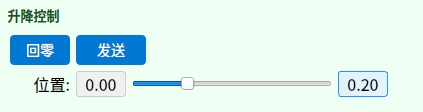
Lifting control
Procedure:
- Quick return-to-zero Click Zero. The spine automatically returns to its preset zero position.
- Adjust the height Move the slider to the target height, and then click Send. The spine moves to the specified position.
Robotic-Arm Motion Control Module#
Overview: This module provides pose control for both MMK2 robotic arms and supports position and orientation adjustment.

Robotic-arm motion control
Safety
Before use, make sure that the head has returned to zero to prevent a collision between the robotic arm and head.
Procedure:
- Reset the joints Click Zero Position to reset all robotic-arm joint angles to zero.
- Starting pose Click Start. The robotic arm returns to its preset safe starting position.
Gripper Control Module#
Overview: This module controls the opening and closing of the grippers on both MMK2 arms for grasping and releasing.

Gripper control
Base Motion Control Module#
Overview: This module provides basic robot-base motion control, including forward and backward movement, rotation, and lateral movement. Distance and angle parameters allow precise pose adjustment.
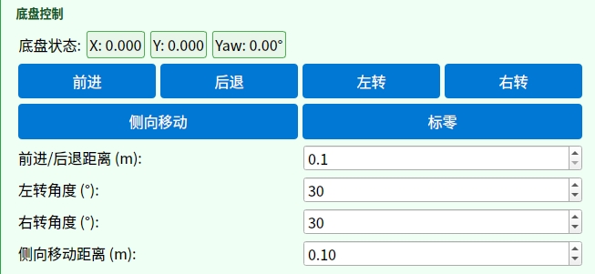
Base motion control
Motion control:
- Set parameters: Enter the step distance or rotation angle in the input field.
- Directional movement:
- Forward/backward: Moves the base by the specified distance along its current direction.
- Turn left/right: Rotates the base in place by the specified angle.
- Lateral movement: Translates the base sideways by the specified distance.
- Calibrate the position: Click Set Zero to set the current base position as the zero reference.
MMK2 Function Module#
Camera Visualization#
Overview: This module displays real-time image data from connected cameras. It supports live monitoring of color images, depth images, and aligned composite views for vision-system debugging and operating-status observation.
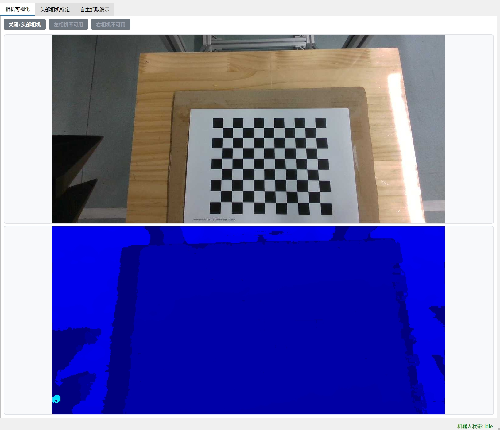
Camera visualization
Instructions
- Operation: Click a camera icon to start that device. Real-time images appear automatically after initialization.
- Switch cameras: Switching to another camera automatically closes the camera that is currently active.
Important
- System resources: When connecting three RealSense cameras simultaneously, configure at least one camera at 480p to balance performance.
- Performance impact: Enabling depth images and depth-color alignment increases computational load and significantly reduces frame rate.
- Changing parameters: Camera parameters (resolution, frame rate, alignment, and so on) cannot be changed dynamically after their initial configuration. Restart the lower-level controller (restart the container or cycle main-unit power) for changes to take effect.
- Depth display: To display depth images, select Align Depth before connecting.
Head-Camera Calibration#
Camera Intrinsic Calibration#
Overview: This module determines camera intrinsics (focal length, principal point, and distortion coefficients) and extrinsics (position and orientation relative to the robot coordinate frame). These parameters are the basis of high-precision visual perception and sensor fusion. Recalibration is recommended after the camera mounting position or environment changes significantly.
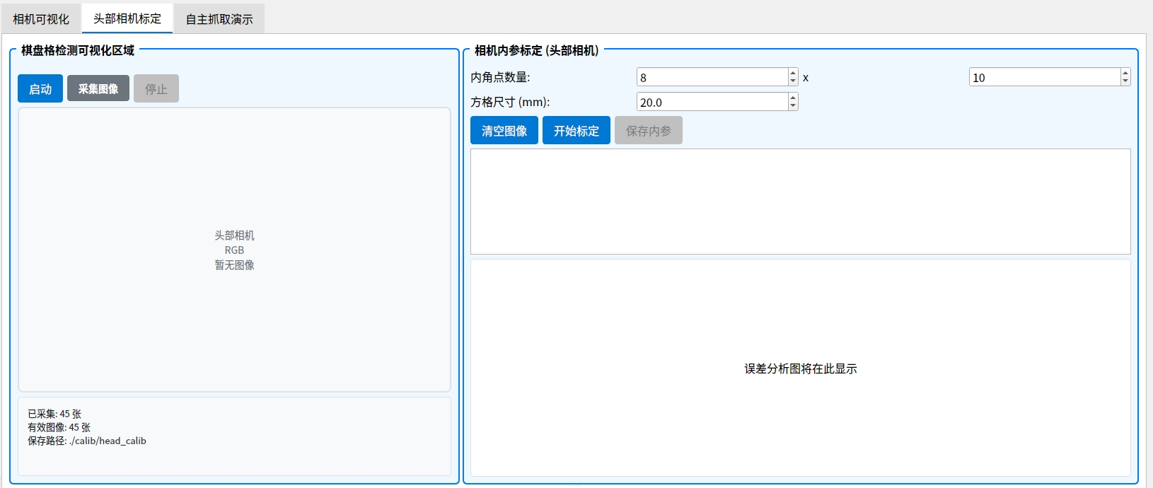
Camera intrinsic calibration interface
Preparation:
- Prepare an A4-size checkerboard calibration target.
- Download the calibration-target PDF and print it at 100% scale.
Calibration procedure:
- Start the camera: Turn on the head camera.
-
Capture images: Obtain images from multiple angles using either method:
- Method 1: Use the motion-control module to move the head to different viewing angles, and click Capture Image.
- Method 2: Keep the head fixed and manually move the calibration target. After confirming that the complete target is clearly visible in the camera view, click Capture Image.
💡 Capture note: The system automatically detects calibration-target corners and saves only valid images. Capture at least 40 valid images for calibration.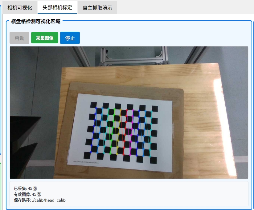
Checkerboard image-capture interface
-
Run calibration: Click Start Calibration. The system generates an error-analysis plot.
-
Evaluate the result: An average error below 0.02 is ideal. Click Save Calibration Results.
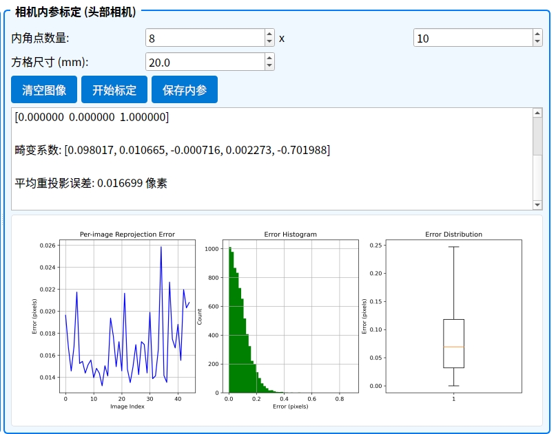
Camera intrinsic calibration result
ArUco Detection Visualization#
Overview: This module detects ArUco markers in real time and overlays reprojection results to provide a visual check of camera-calibration accuracy.
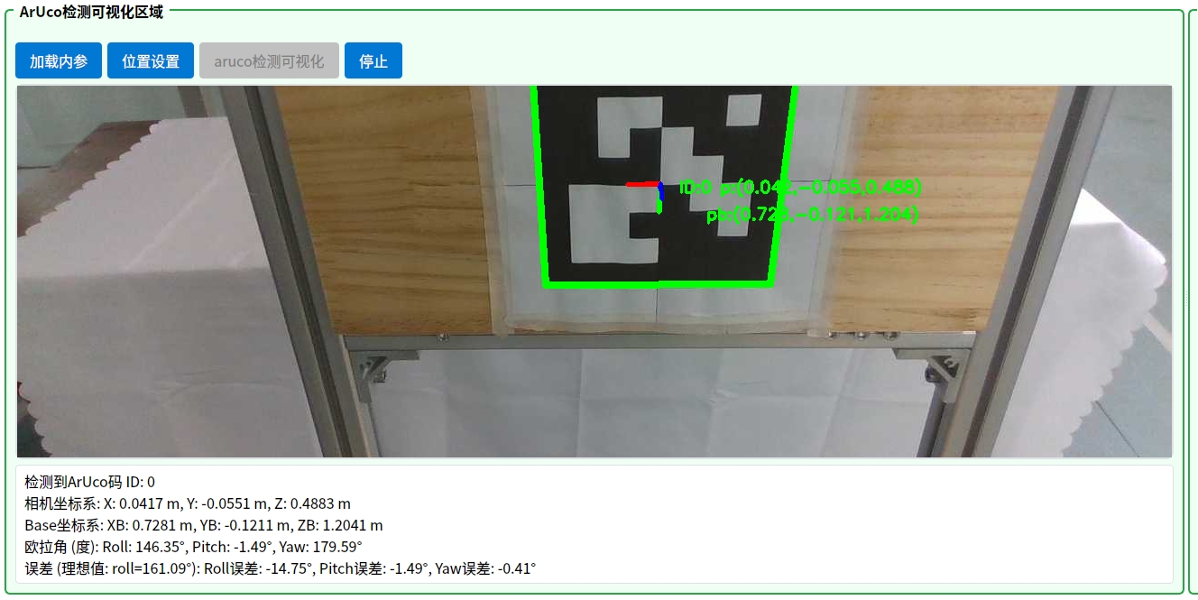
ArUco detection
Procedure:
-
Prepare the calibration target:
- Prepare an A4-size calibration target.
- Download the ArUco PDF, print it, and attach it so that it is completely horizontal and vertical.
-
Load parameters: Click Load Intrinsics to import the saved head-camera calibration parameters.
-
Set the robot pose:
- Set both arms to their zero positions.
- Adjust the spine height and set the head to its zero position.
- Make sure the head camera can see the complete ArUco marker.
-
Run detection: Click ArUco Detection Visualization to begin real-time detection.
-
Verify accuracy: Make sure all error values are <3°. Otherwise, extrinsic calibration is recommended.
ArUco Extrinsic Calibration#
Overview: This module determines the rigid transformation (rotation and translation) between the camera and robot coordinate frames. It is essential for vision-guided grasping, hand-eye coordination, and spatial positioning. Recalibration is recommended after the camera or calibration-target mounting position changes.
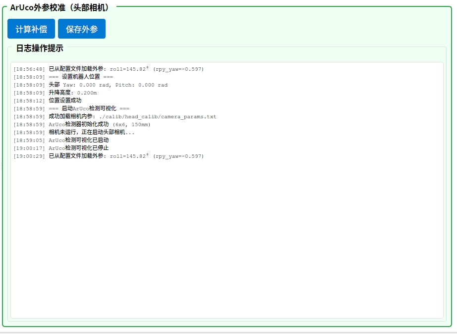
ArUco extrinsic calibration
Calibration procedure:
-
Calculate compensation: Click Calculate Compensation. The program automatically samples data and calculates the compensation values.
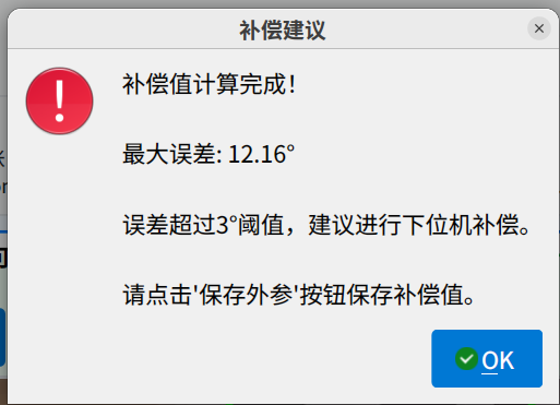
Compensation calculation
-
Save extrinsics: Click Save Extrinsics, and adjust the compensation values as prompted.
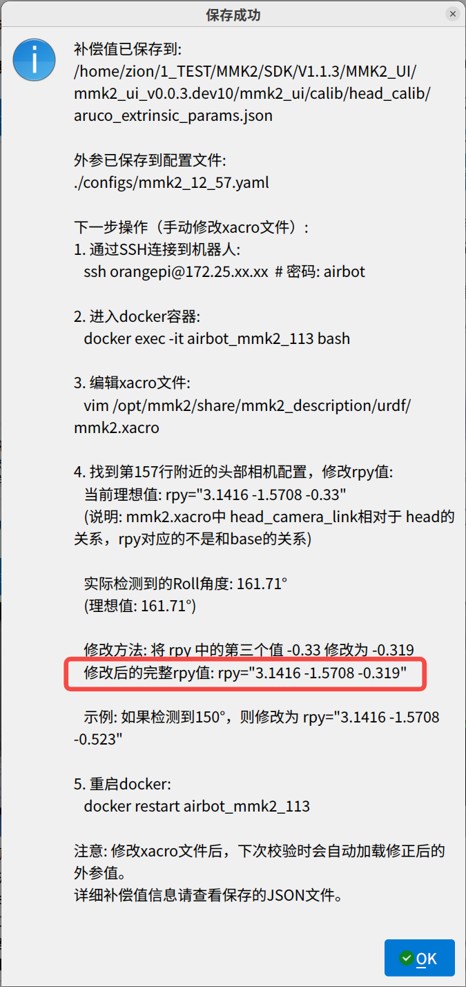
Extrinsic compensation
-
Verify the result: Click Calculate Compensation again and confirm that the displayed values are within the allowed range.
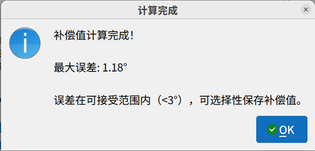
Compensation result
Autonomous Grasping Demo Module#
Overview: This module provides complete grasp-task management, including configuration, execution, and real-time monitoring of robot grasping operations.
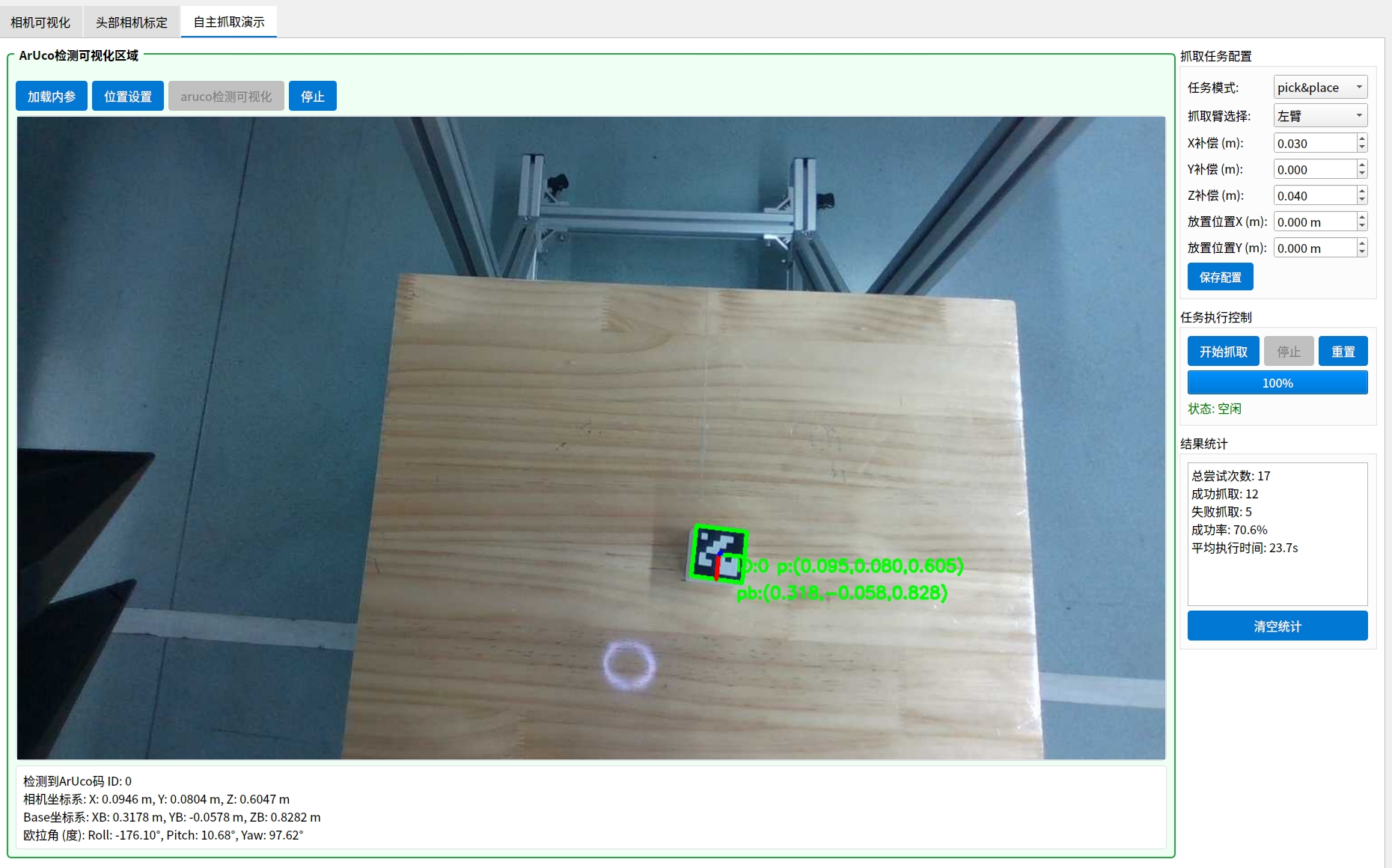
Autonomous grasping
Required Preparation
Complete the following configuration before starting the task:
- Camera: Set the head-camera resolution to 720p.
- Base calibration: Open the base control module and click Set Zero.
- Robotic-arm reset: Move the lifting mechanism and robotic arms to their zero positions.
Recommended Grasping Parameters
Z-axis compensation:
- Before grasping, set the Z-axis compensation value to at least 0.1.
- A larger compensation value helps prevent collisions between the gripper and target object.
-
Preparation: Print the ArUco PDF on A4 paper at actual size, cut out the markers, and attach them to a 4cm³ cube or an object with equal sides.
-
Visualization area:
-
Click Load Intrinsics to load the saved head-camera calibration parameters.
-
Click ArUco Detection Visualization. The system automatically adjusts the image-display size for the best visualization.
-
Click Position Settings and adjust the head and lifting positions so the complete executable area is visible in the image.
-
-
Configure the grasping task:
-
In the grasping-task configuration, select the required task mode and executing arm. Adjust other parameters according to the difference between the first grasp position and the actual target.
-
Click Save Configuration to save the parameters.
-
-
Control task execution:
-
Click Start Grasping and observe the difference between the first grasp position and the actual target. Fine-tune the relevant parameters in the grasping-task configuration and continue trying until the result is satisfactory.
-
Click Stop to end the current task.
-
Click Reset to return the robotic arm to its starting position.
-
-
Result statistics: Click Clear Statistics to reset the statistics.
Precautions#
-
After clicking a function button, wait until the current operation is fully complete before starting another operation. Otherwise, the interface may stop responding.
-
Before using the head control module, move both robotic arms to the Start position to prevent collisions.
-
Before using the robotic-arm control module, return the head to zero to prevent collisions.
-
Before using the lifting control module, move both robotic arms to their Start or zero positions to prevent collisions.
-
If camera parameters need adjustment, restart the Docker container or robot for the new configuration to take effect.
-
Before using Autonomous Grasping, set the base zero, configure the head-camera resolution as 720p, and move the lifting mechanism and robotic arms to their zero positions.
-
When using Autonomous Grasping, control the lifting distance carefully to prevent collisions with both arms. A movement of no more than 0.05m at a time is recommended.
-
Recalibrate the head camera and ArUco extrinsics after the head-camera mounting position or environment changes significantly.